104
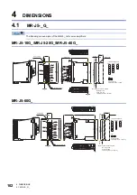
4 DIMENSIONS
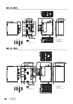
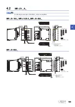
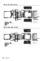
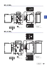
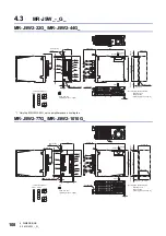
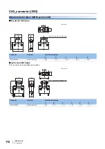
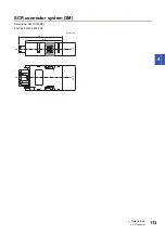
4.1 MR-J5-_G_
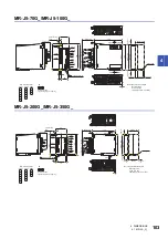
MR-J5-500G_
MR-J5-700G_
105
93
6
6
6
7.5
235
7.5
250
6
200
6
CNP1A
CNP1B
CNP2
CNP3
CN1A
CN1B
CN5
CN6
CN3
CN8
CN2
CN2L
CN4
235 ± 0.5
93 ± 0.5
PE
P4
P3
N-
CNP1B
L1
L3
L2
CNP1A
CNP2 CNP3
P+
D
L21
C
L11
U
W
V
Mounting hole location diagram
Mounting screw
Screw size: M5
Tightening torque: 3.24 [N•m]
Exhaust
Cooling
fan
Intake
Approx. 80
Approx. 105
Approx.
6
Approx.
6
Approx.
7.5
Approx. 250
4-M5 screw
Approx.
7.5
Screw size: M4
Tightening torque: 1.2 [N•m]
Terminal assignment
Locking tab
Grounding terminal
φ
6 mounting
hole
200
6
170
160
5
5
5
7.5
285
7.5
300
5
CNP1A
CNP1B
CNP2
CNP3
CN1A
CN1B
CN5
CN6
CN8
CN3
CN2
CN2L
CN4
285 ± 0.5
160 ± 0.5
PE
P4
P3
N-
CNP1B
L1
L3
L2
CNP1A
CNP2 CNP3
P+
D
L21
C
L11
U
W
V
φ
6 mounting
hole
Grounding terminal
Approx. 80
Exhaust
Cooling
fan
Intake
Approx.
5
Approx.
5
Approx. 170
4-M5 screw
Approx. 300
Approx.
7.5
Locking tab
Approx.
7.5
Mounting hole location diagram
Mounting screw
Screw size: M5
Tightening torque: 3.24 [N•m]
Screw size: M4
Tightening torque: 1.2 [N•m]
Terminal assignment
Содержание Melservo-J5 MR-J5 Series
Страница 1: ...MR J5 User s Manual Hardware MR J5 _G_ MR J5W_ _G_ MR J5 _A_ Mitsubishi Electric AC Servo System ...
Страница 2: ......
Страница 441: ...12 USING A FULLY CLOSED LOOP SYSTEM 12 7 Absolute position detection system 439 12 MEMO ...
Страница 445: ......


