176
6 OPTIONS AND PERIPHERAL EQUIPMENT
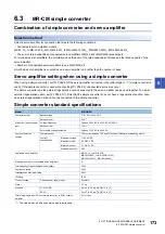
6.3 MR-CM simple converter
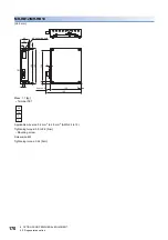
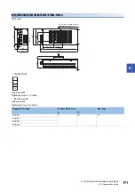
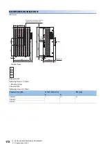
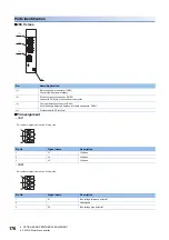
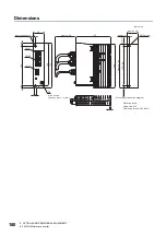
Parts identification
■
200 V class
■
Pin assignment
• CNP1
• CNP2
No.
Name/Application
(1)
Main circuit power connector (CNP1)
Connect the input power supply.
(2)
PN bus connection connector (CNP2)
Connect to P4/N- pin of next-axis servo amplifier.
(3)
Overheat detection connector (CN10)
If overheating is detected, between terminals changes to "OPEN".
(4)
Protective earth PE terminal
Pin No.
Signal name
Description
1
L1
L1 phase
2
L2
L2 phase
3
L3
L3 phase
Pin No.
Signal name
Description
1
N-
Bus voltage reference potential
2
Unassigned
3
P4
Bus voltage plus potential
(1)
L1
L2
L3
N-
P4
T1
T2
(2)
(3)
(4)
1
2
3
Pin number diagram viewed from Wiring side
1
2
3
Pin number diagram viewed from Wiring side
Содержание Melservo-J5 MR-J5 Series
Страница 1: ...MR J5 User s Manual Hardware MR J5 _G_ MR J5W_ _G_ MR J5 _A_ Mitsubishi Electric AC Servo System ...
Страница 2: ......
Страница 441: ...12 USING A FULLY CLOSED LOOP SYSTEM 12 7 Absolute position detection system 439 12 MEMO ...
Страница 445: ......


