80
3 SIGNALS AND WIRING
3.5 Signal (device) explanation
Output device explanation [A]
■
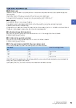
MBR (Electromagnetic brake interlock)
MBR is off in the servo-off state or at an alarm occurrence.
If using the device, set an operation delay time of the electromagnetic brake in [Pr. PC16].
For details. refer to "Electromagnetic brake interlock function" in the following manual.
MR-J5 User's Manual (Function)
■
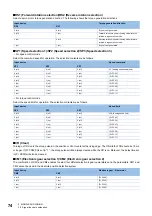
VLC (Limiting speed)
In the torque mode, VLC will turn on if the speed reaches the value limited with any of [Pr. PC05] to [Pr. PC11] or VLA (Analog
speed limit). VLC will turn off in the servo-off state.
■
ZSP (Zero speed detection)
If the servo motor speed is the zero speed or less, ZSP will turn on. The zero speed can be changed with [Pr. PC17]. The
following shows an example when the initial value (50) is set in [Pr. PC17].
ZSP will turn on when the servo motor speed is reduced to 50 r/min (at (1)), and will turn off when the servo motor is increased
to 70 r/min again (at (2)).
ZSP will turn on when the servo motor is decelerated again to 50 r/min (at (3)), and will turn off when the servo motor speed
reaches -70 r/min (at (4)).
The range from the point when the servo motor speed has reached the on-level and ZSP turns on, to the point when the
speed has increased again and reached the off-level is called a hysteresis width.
The hysteresis width is 20 r/min for this servo amplifier.
If using a linear servo motor, replace [r/min] with [mm/s].
■
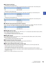
TLC (Limiting torque)
When torque is generated, TLC will turn on if the torque reaches the torque limit value set with any of [Pr. PA11], [Pr. PA12], or
TLA (Analog torque limit).
■
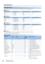
ABSB0 (ABS transmission data bit 0)
This is used to output ABS transmission data bit 0. If the absolute position detection system by DIO is selected while [Pr.
PA03.0] is set to "1", ABSB0 will be assigned to the CN3-22 pin only in the ABS transfer mode.
Page 263 ABSOLUTE POSITION DETECTION SYSTEM
■
ABSB1 (ABS transmission data bit 1)
This is used to output ABS transmission data bit 0. If the absolute position detection system by DIO is selected while [Pr.
PA03.0] is set to "1", ABSB1 will be assigned to the CN3-23 pin only in the ABS transfer mode.
Page 263 ABSOLUTE POSITION DETECTION SYSTEM
■
ABST (ABS transmission data ready)
This is used to output ABS transmission data ready. If the absolute position detection system by DIO is selected while [Pr.
PA03.0] is set to "1", ABST will be assigned to the CN3-25 pin only in the ABS transfer mode.
Page 263 ABSOLUTE POSITION DETECTION SYSTEM
OFF
ON
20 r/min
[Pr. PC17]
20 r/min
-70 r/min
-50 r/min
50 r/min
70 r/min
0 r/min
[Pr. PC17]
ZSP
(1)
(2)
(4)
(3)
OFF level
Forward
rotation
direction
(Hysteresis width)
ON level
Servo motor
speed
ON level
Reverse
rotation
direction
(Hysteresis width)
OFF level
(Zero speed detection)
Содержание Melservo-J5 MR-J5 Series
Страница 1: ...MR J5 User s Manual Hardware MR J5 _G_ MR J5W_ _G_ MR J5 _A_ Mitsubishi Electric AC Servo System ...
Страница 2: ......
Страница 441: ...12 USING A FULLY CLOSED LOOP SYSTEM 12 7 Absolute position detection system 439 12 MEMO ...
Страница 445: ......


