Chapter 6 - Parameter Description [I/O]
121
[Speed-L, Speed-M, Speed-H]
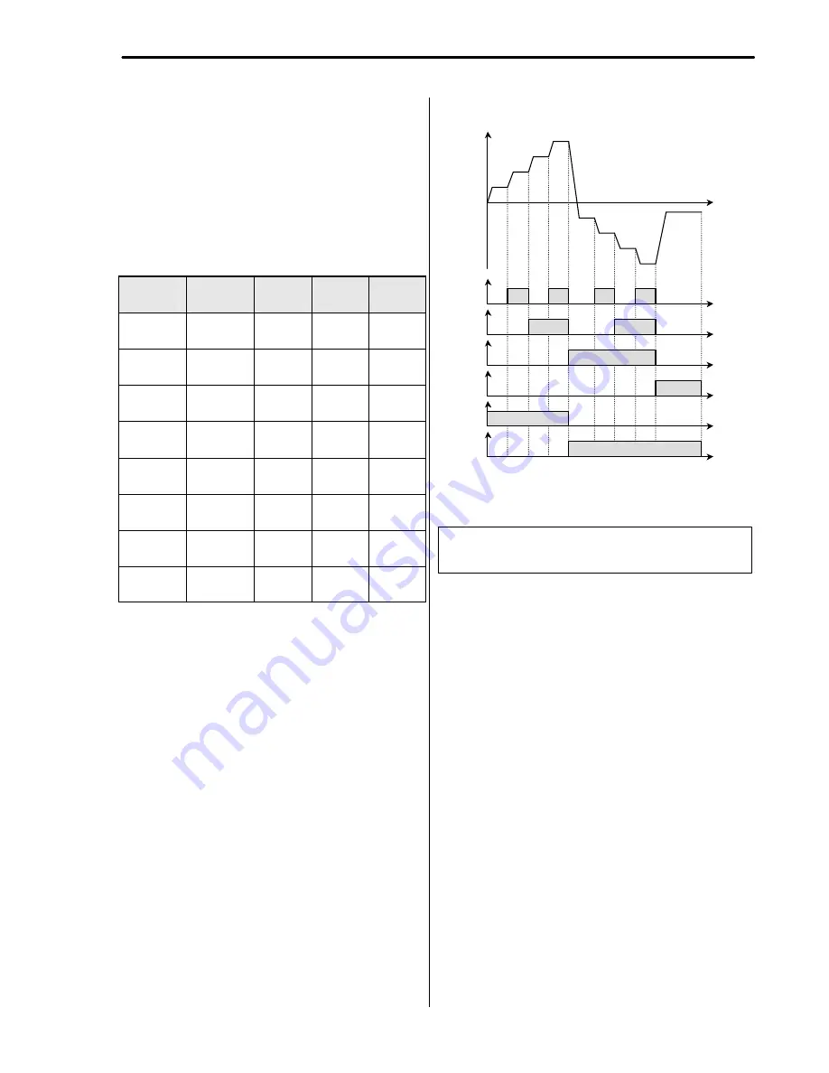
By setting P1, P2, P3 terminals to ‘Speed-L’, ‘Speed-M’
and ‘Speed-H’ respectively, inverter can operate at the
preset frequency set in DRV-05 ~ DRV-07 and I/O-20 ~
I/O-24.
The step frequencies are determined by the combination
of P1, P2 and P3 terminals as shown in the following
table.
Step
Frequency
Parameter
Code
Speed-H
(P3)
Speed-M
(P2)
Speed-L
(P1)
Step Freq-
0
DRV-00
0
0
0
Step Freq-
1
DRV-05
0
0
1
Step Freq-
2
DRV-06
0
1
0
Step Freq-
3
DRV-07
0
1
1
Step Freq-
4
I/O-21
1
0
0
Step Freq-
5
I/O-22
1
0
1
Step Freq-
6
I/O-23
1
1
0
Step Freq-
7
I/O-24
1
1
1
0: OFF, 1: ON
☞
I/O-20 [Jog Frequency] can be used as one of the step
frequencies.
☞
If the ‘Jog’ terminal is ON, inverter operates to Jog
frequency regardless of other terminal inputs
.
[Multi-Step Frequency Operation]
☞
Note:
The frequency for ‘Speed 0’ is determined by DRV-
04.
P1-CM
ON
ON
Output Frequency
Time
Time
P2-CM
ON
ON
Time
P3-CM
ON
Time
JOG-CM
ON
Time
FX-CM
ON
Time
RX-CM
ON
Time
ON
ON
Step
0
Step
1
Step
2
Step
3
Step
4
Step
5
Step
6
Step
7
Jog
Related Functions:
DRV-05 ~ DRV-07 [Step Frequency]
I/O-20 [Jog Frequency]
I/O-20 ~ I/O-24 [Step Frequency]
Morek IT OÜ, Rauna 24, 76506 Saue Harjumaa, Estonia. www.morek.eu Tel. +372 604 1423 Fax +372 604 1447 [email protected]


