Chapter 6 - Parameter Description [FU2]
116
This must be set when using an external DB resistor.
The duty is calculated by ‘%ED=Decel time * 100 /
(Accel time + Steady speed time + Decel time + Stop
status time)’.
FU2-79: Software Version
Displays the software version. This will vary depending
on software version integrated.
FU2-81 ~ FU2-90: 2
nd
Motor Related Functions
These functions are displayed only when one of the
multifunction inputs is set at ‘2nd func’ in I/O-12 to I/O-14.
When using two motors with an inverter by exchanging
them, different values can be set for the 2
nd
motor by
using the multifunction input terminal.
Following table is the 2
nd
functions corresponding to the
1
st
functions.
2
nd
Functions
1
st
Functions
Description
FU2-81
[2nd Acc time]
DRV-01
[Acc. time]
Acceleration time
FU2-82
[2nd Dec time]
DRV-02
[Dec. time]
Deceleration time
FU2-83
[2nd BaseFreq]
FU1-21
[Base freq]
Base Frequency
FU2-84
[2nd V/F]
FU1-29
[V/F Pattern]
Volts/Hz mode
FU2-85
[2nd F-boost]
FU1-27
[Fwd Boost]
Forward torque boost
FU2-86
[2nd R-boost]
FU1-28
[Rev Boost]
Reverse torque boost
FU2-87
[2nd Stall]
FU1-60
[Stall Level]
Stall prevention level
FU2-88
[2nd ETH 1min]
FU1-51
[ETH 1min]
ETH level for 1 minute
FU2-88
[2nd ETH cont]
FU1-52
[ETH cont]
ETH level for continuous
FU2-90
[2nd R-Curr]
FU2-33
[Rated-Curr]
Motor rated current
l
The 1
st
functions are applied if the multifunction terminal
is not defined to ‘2nd Func’ or if it is not ON. The 2
nd
function parameters are applied when the multifunction
input terminal set to ‘2nd Func’ is ON. Parameters not
listed on the table above are applied to the 2
nd
motor as
to the 1
st
motor.
l
Exchange the motor connection from the 1
st
motor to the
2
nd
motor or the opposite when the motor is stopped.
Over voltage or over current fault can occur when the
motor connection is exchanged during operation.
l
The ‘User V/F’ function of FU1-29 [V/F Pattern] is used
for both the 1st motor and the 2nd motor.
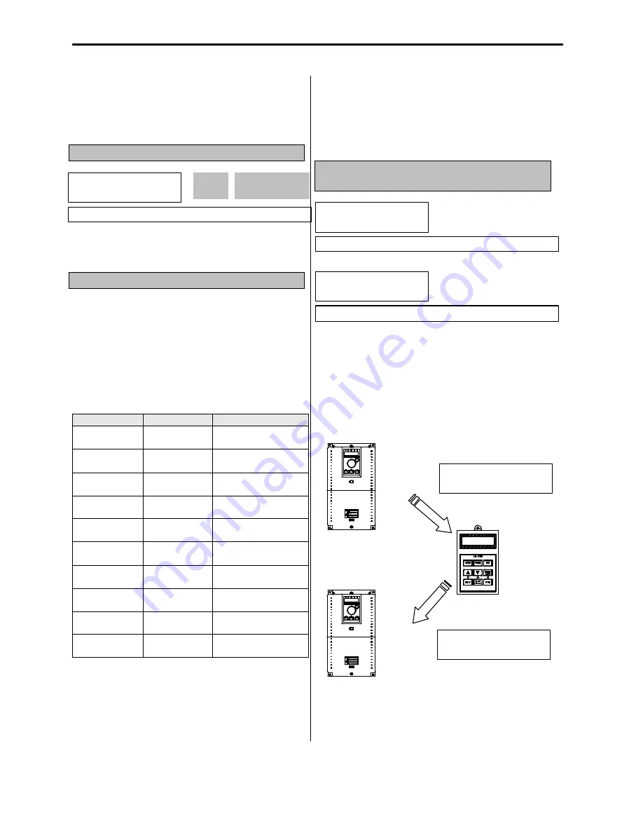
FU2-91: Parameter Read
FU2-92: Parameter Write
This is useful for programming multiple inverters to have
same parameter settings. The LCD keypad can read
(upload) the parameter settings from the inverter
memory and can write (download) them to other
inverters. This
function is only available with LCD
keypad.
i S 5
VARIABLE FREQUENCY DRIVE
Risk of Injury or Electric Shock
Risk of Electric Shock
Risk of Electric Shock
WARNING
E X T
RUN
ESC
SHIFT
F U 2
FU1
DRV
E N T
PROG
RESET
STOP
L E - 2 0 0
I / O
i S 5
VARIABLE FREQUENCY DRIVE
Risk of Injury or Electric Shock
Risk of Electric Shock
Risk of Electric Shock
WARNING
E X T
RUN
ESC
SHIFT
F U 2
FU1
DRV
E N T
PROG
RESET
STOP
L E - 2 0 0
I / O
FU2? S/W Version
79 Ver X.X
X.X
79
Factory Default:
Ver. X.X
X.X
FU2? Para. read
91 --- No ---
Factory Default:
No
FU2? Para. write
92 --- No ---
Factory Default:
No
FU2? Para. read
91 --- Yes ---
Parameter Upload
Parameter Download
FU2? Para. write
92 --- Yes ---
Morek IT OÜ, Rauna 24, 76506 Saue Harjumaa, Estonia. www.morek.eu Tel. +372 604 1423 Fax +372 604 1447 [email protected]


