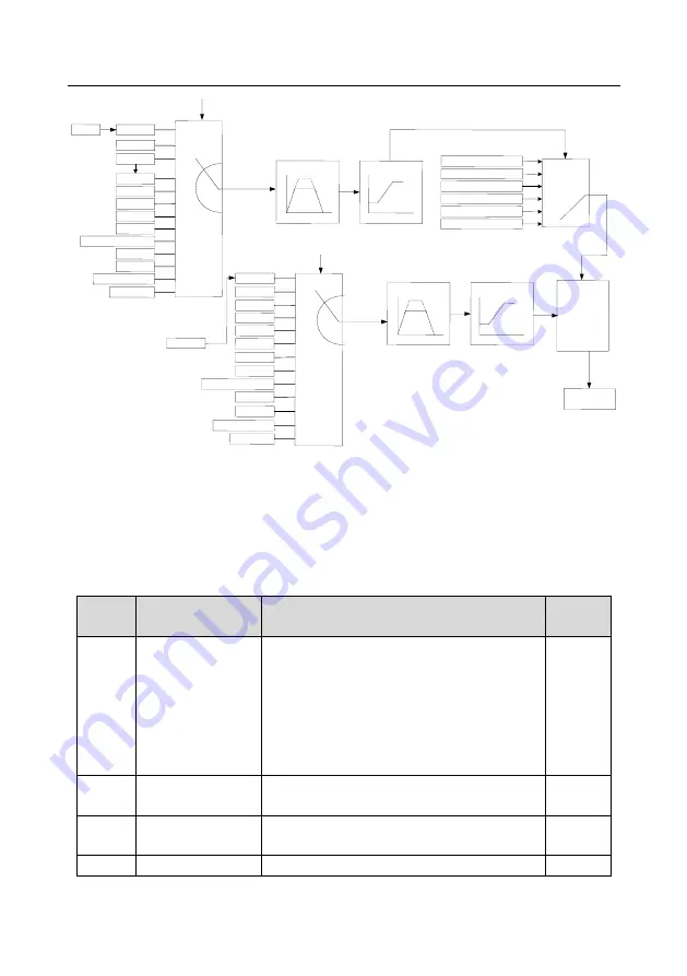
Goodrive350-19 series VFD for crane
Basic operation guidelines
-147-
V /F curve
Straight-type V/F curve
Multi-point V/F curve
Customized V/F curve
Torque-down V/F curve (power
2.0)
Torque-down V/F curve (power
1.7)
Torque-down V/F curve (power
1.3)
PWM output
Frequency
setting
Voltage
setting
P04.29 voltage acceleration time
P04.30 voltage deceleration time
P04.31 output max. voltage
P04.32 output min. voltage
P00.11 acceleration time 1
P00.12 deceleration time 1
P00.04 running frequency upper limit
P00.05 running frequency lower limit
P04.00 V/F curve setting of motor 1
0
1
2
3
4
5
6
7
8
9
10
Keypad
AI1
PROFIBUS\CANopen
MODBUS
PID
Multi-step speed
HDIA
AI3
AI2
Ethernet
HDIB
P04.27 (voltage setting
channel)
P04.28
0
1
2
3
4
5
6
7
8
9
10
11
Keypad
AI1
PROFIBUS\CANopen
MODBUS
PID
Multi-step speed
HDIA
AI3
AI2
Ethernet
P00.06 (Setting channel of A frequency
command)
Frequency set through keypad
P00.10
0
1
2
3
4
5
EtherCat/Profinet
PLC card
HDIB
EtherCat/Profinet
PLC card
11
12
12
When selecting the customized V/F curve function, you can specify the setting channels and
acceleration/deceleration time of voltage and frequency respectively, which form a real-time V/F
curve in combination manner.
Note: This type of V/F curve separation can be applied in various variable-frequency power
sources. However, exercise caution when setting parameters as improper settings may cause
equipment damage.
Function
code
Name
Description
Default
P00.00
Speed control mode
0: Sensorless vector control (SVC) mode 0
1: Sensorless vector control (SVC) mode 1
2: Space voltage vector control mode
3: Closed-loop vector control mode
Note: Before using a vector control mode (0, 1, or
3), enable the VFD to perform motor parameter
autotuning first.
2
P00.03
Max. output
frequency
P00.04
–400.00Hz
50.00Hz
P00.04
Upper limit of running
frequency
P00.05
–P00.03
50.00Hz
P00.05 Lower limit of running 0.00Hz
–P00.04
0.00Hz


