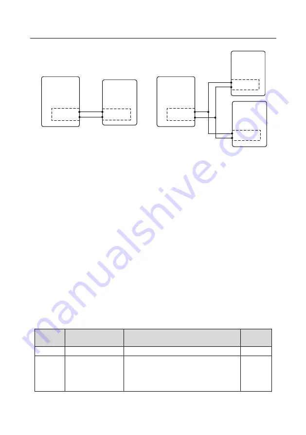
Goodrive350-19 series VFD for crane
Commissioning guidelines
-91-
5.13.1 Wiring
VFD
Lifting
CAN master/slave
communication card
CANH
CANL
VFD
Trolley
CANH
CANL
VFD
Lifting
CANH
CANL
VFD
Long travel
mechanism
CANH
CANL
VFD
Trolley
CANH
CANL
Tower crane application
Factory/port crane application
CAN master/slave
communication card
CAN master/slave
communication card
CAN master/slave
communication card
CAN master/slave
communication card
5.13.2 Commissioning procedure of the anti-sway function for tower cranes
1. Enable the anti-sway function by setting the trolley VFD function code P85.00=1 or S terminal
function 90.
2. Set P85.01 and P85.02 of the trolley VFD.
3. Set the trolley VFD CAN communication: P28.00=2, configured as the slave, and P28.02=0x116,
the height sent from the master to the slave.
4. Configure the lifting VFD to measure the height. For details, see section 5.15. After the height
measuring, check whether P94.32 (height that the slave receives) and P94.05 (height that the
master measures) are the same.
5. Perform low-speed trial run.
Note: The rope length can be compensated through P85.03. When there is gear switchover
need, you can adjust the value of P85.04.
5.13.3 Commissioning procedure of the anti-sway function for factory cranes
1. Set lifting and trolley VFD parameters, which are the same as section 5.12.2.
2. Set bridge VFD parameters, which are the same as trolley VFD parameters.
5.13.4 Macro parameters
Trolley and long-travel mechanism VFD parameters
Function
code
Name
Description
Setting
P85.00
Enabling anti-sway
1: Enable
1
P85.01
Pendulum reduction
mode
0
–3
0: Pendulum reduction mode 0
1: Pendulum reduction mode 1
2: Pendulum reduction mode 2
0


