


INTEC GmbH
22/12/2016
Lift controller MLC 8000
Operating manual V2.0
129/196
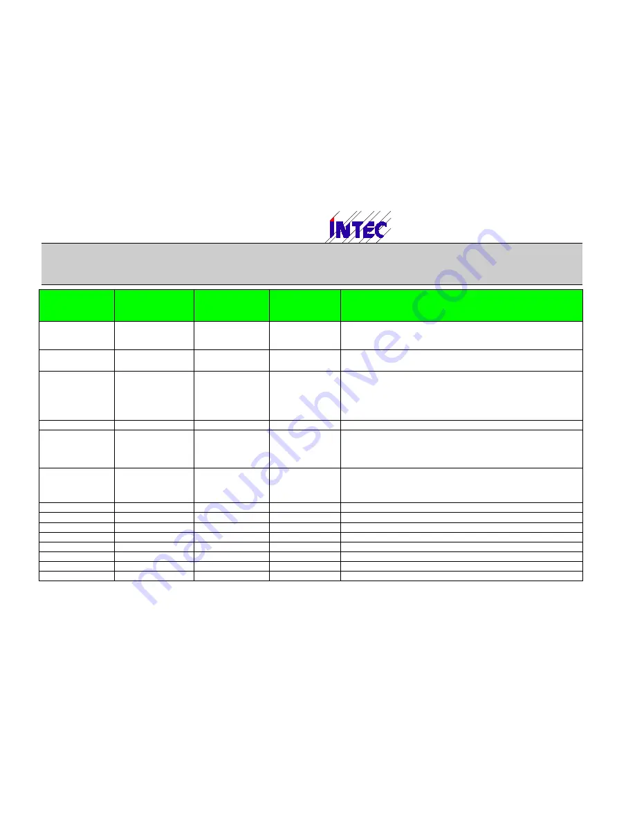
Main function
Sub function/
Direction/
Floor
Floor
Doors
Description
Targ.call dn
Callfloor
Targetfloor
Doors in
Call- and
Target floor
See above; landing call in down direction is set.
Vis.request
Callfloor
-
Doors
Enables a call to the programmed floor and doors.
For more detailled description refer to "Special param. - Visitor floors" in chapter
"menu structure"
Hazard.call
Floor
Doors
Special control sequence for hazardous goods.
Input to set a call for transportation of hazardous goods.
If no separate door open push exists (Parameter „Hazard transport“ -> „Door
input“ is set to „no“)this input may also be used to open / close the doors if the
lift is located in the programmed floor.
Additional settings see description of parameter set „Special param. - Hazard
transport“
Hazard.door
Floor
Doors
Button to open or close the doors in hazardous transportation mode.
Inspect.
- On
- Up
- Down
- Slow
-
-
Control inputs for inspection control.
If no slow input is programmed the lift always runs with normal inspection speed
vL (see parameter "Speed signals") in inspection mode; only in final floors the
speed is reduced to vIL.
Door test
-
-
Input to start door test mode.
In door test mode it is possible to operate the doors with inspection switches
(Up/Down).
Additional it is possible to start the door test mode by pressing inspection up
and down push together for at least 5s while inspection is switched on.
Pos.
SGM
-
-
Input for door zone switch SGM
SGO
-
-
Input for upper door zone switch SGO
SGU
-
-
Input for lower door zone switch SGU
VO
-
-
Input for upper prelimit switch VOO
VU
-
-
Input for upper prelimit switch VOO
SGV
-
-
Input for slow down switch SGS
SGE
-
-
Input for reference switch SGE
Car light
-
-
-
Überwachungseingang Fahrkorblichtspannung


