


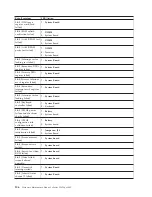

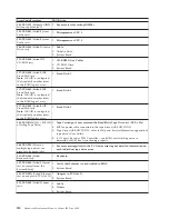

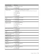


Beep/Symptom
FRU/Action
One Long and One
Short Beep
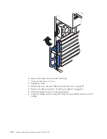
1.
Video adapter (if present)
2.
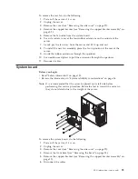
System Board
One Long and Two
Short Beeps
1.
Video adapter (if present)
2.
System Board
Two Long and Two
Short Beeps
1.
Video adapter
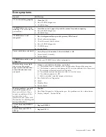
No beep symptoms
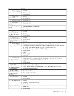
No Beep Symptom
FRU/Action
No beep and the system
operates correctly.
1.
Check speaker cables
2.
Speaker
3.
System board
No Beeps occur after
successfully completing
POST
1.
Check speaker connections
2.
Speaker
3.
System board
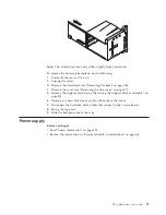
No ac power
1.
Check the power cord.
2.
Power supply.
No beep and no video
1.
See “Undetermined problems” on page 117
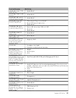
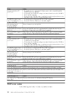
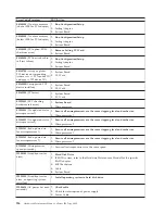
Diagnostic error codes
Note:
In the following error codes, if
XXX
is
000
,
195
, or
197
do not
replace a FRU.
The description for these error codes are:
000
The test passed.
195
The
Esc
key was pressed to abort the test.
197
This is a warning error and may not indicate a hardware failure.
For all error codes, replace/follow the FRU/Action indicated.
Error Code/Symptom
FRU/Action
001-XXX-000
(Failed core
tests)
1.
System Board
001-XXX-001
(Failed core
tests)
1.
System Board
001-250-000
(Failed System
Board ECC)
1.
System Board
001-250-001
(Failed System
Board ECC)
1.
System Board
005-XXX-000
(Failed Video
test)
1.
Video Adapter (if installed)
2.
System Board
011-XXX-000
(Failed COM1
Serial Port test)
1.
System Board
108
Hardware Maintenance Manual: xSeries 220 Type 8645
Содержание 8645 - Eserver xSeries 220
Страница 1: ...Hardware Maintenance Manual xSeries 220 Type 8645...
Страница 2: ......
Страница 3: ...Hardware Maintenance Manual xSeries 220 Type 8645...
Страница 18: ...10 Hardware Maintenance Manual xSeries 220 Type 8645...
Страница 36: ...28 Hardware Maintenance Manual xSeries 220 Type 8645...
Страница 58: ...50 Hardware Maintenance Manual xSeries 220 Type 8645...
Страница 102: ...94 Hardware Maintenance Manual xSeries 220 Type 8645...
Страница 141: ...Related service information 133...
Страница 142: ...134 Hardware Maintenance Manual xSeries 220 Type 8645...
Страница 143: ...Related service information 135...
Страница 144: ...136 Hardware Maintenance Manual xSeries 220 Type 8645...
Страница 145: ...Related service information 137...
Страница 146: ...138 Hardware Maintenance Manual xSeries 220 Type 8645...
Страница 147: ...Related service information 139...
Страница 148: ...140 Hardware Maintenance Manual xSeries 220 Type 8645...
Страница 158: ...150 Hardware Maintenance Manual xSeries 220 Type 8645...
Страница 159: ...Related service information 151...
Страница 160: ...152 Hardware Maintenance Manual xSeries 220 Type 8645...
Страница 167: ......


