12.
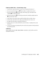
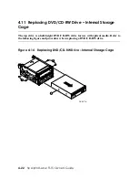
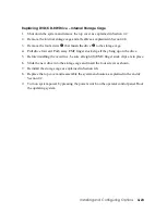
Pull the two spring-loaded pull pins
o
and lower the storage bay until the pins snap
into place.
13.
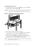
Replace the top cover and reassemble the system enclosure as explained at the end of
Section 4.2.
14.
Turn on system power by pressing the power switch on the operator control panel. Boot
the operating system.
4.4
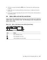
Status LEDs on Front Access Drives
Storage drives in the optional front access storage cage provide three status LEDs that
display activity, power, and drive fault. The following figure shows the position and
purpose of these LEDs.
Figure 4–6 LEDs on the Front Access Drive (Front View)
MR0308B
LED Status
Green indicates activity.
Green indicates drive state.
Amber indicates drive state fault.
Installing and Configuring Options
4-9
Содержание AlphaServer TS15
Страница 6: ......
Страница 34: ...Figure 1 14 VGA Monitor Connected to Optional Video Card B 1 2 A MR0647 1 18 hp AlphaServer TS15 Owner s Guide ...
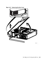
Страница 91: ...Figure 4 3 Removing the Top Cover A 2 1 4 5 3 MR0642 Installing and Configuring Options 4 5 ...
Страница 188: ...Figure 6 4 Setup for RMC with VGA Monitor A 1 2 B MR0626 ENET VGA 6 10 hp AlphaServer TS15 Owner s Guide ...
Страница 213: ...Figure 6 5 RMC Jumpers Default Positions Using the Remote Management Console 6 35 ...
Страница 252: ......


