


Fluorolog-3 v. 2.2 (31 Jul 2002)
Producing Correction Factors
11-11
Because this file was created with the high voltage off, each intensity value is
zero. The irradiance values calculated in a previous step will be entered into the
intensity locations for each wavelength.
9
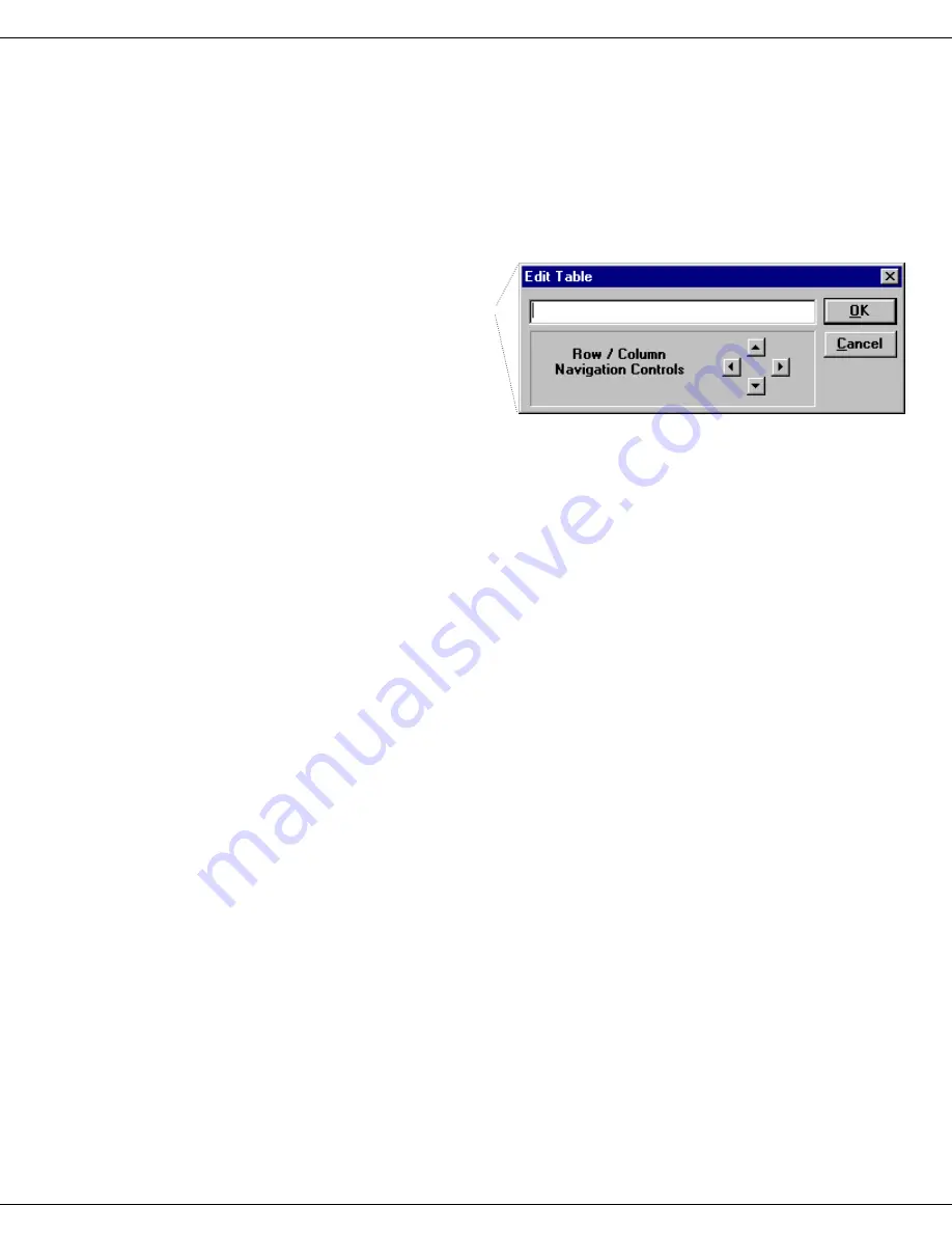
Click on the value to be changed. From the
keyboard, type in the calculated irradiance
value.
As soon as you begin to
type, the
Edit Table
dialog
box will appear:
Click on the up and down
arrows to move within a
column, or click on the left
and right arrows to move
between columns. After all of the irradiance values have been entered,
10
Click on OK.
The
CRE
file has the irradiance values incremented every 50 nm. To calculate
the actual correction factors, the irradiance file needs to have a 5-nm increment.
11
Using the instructions presented above, create
another file.
(Keep the high voltage off.) This time, however, enter 5 nm for the
Increment
instead of 50 nm. Name this file
IRR
.
When this scan is complete, the scan range will be from 290–850 nm with an
increment of 5 nm. All data points will have intensity values of 0 cps.
12
Using the Arithmetic menu, add the constant 1
to the
IRR
file and resave it as
IRR
.
13
Multiply
IRR
by
CRE
and resave it as
IRR
.
This causes the original
IRR
file to be overwritten. The irradiance values will
be spaced every 5 nm as opposed to every 50 nm. The
IRR
file should look
similar to this:
Artisan Technology Group - Quality Instrumentation ... Guaranteed | (888) 88-SOURCE | www.artisantg.com


