19
3.16 THE SHAFT LOCK OF THE MOTOR DRIVE VIBRATORY ASSEMBLY
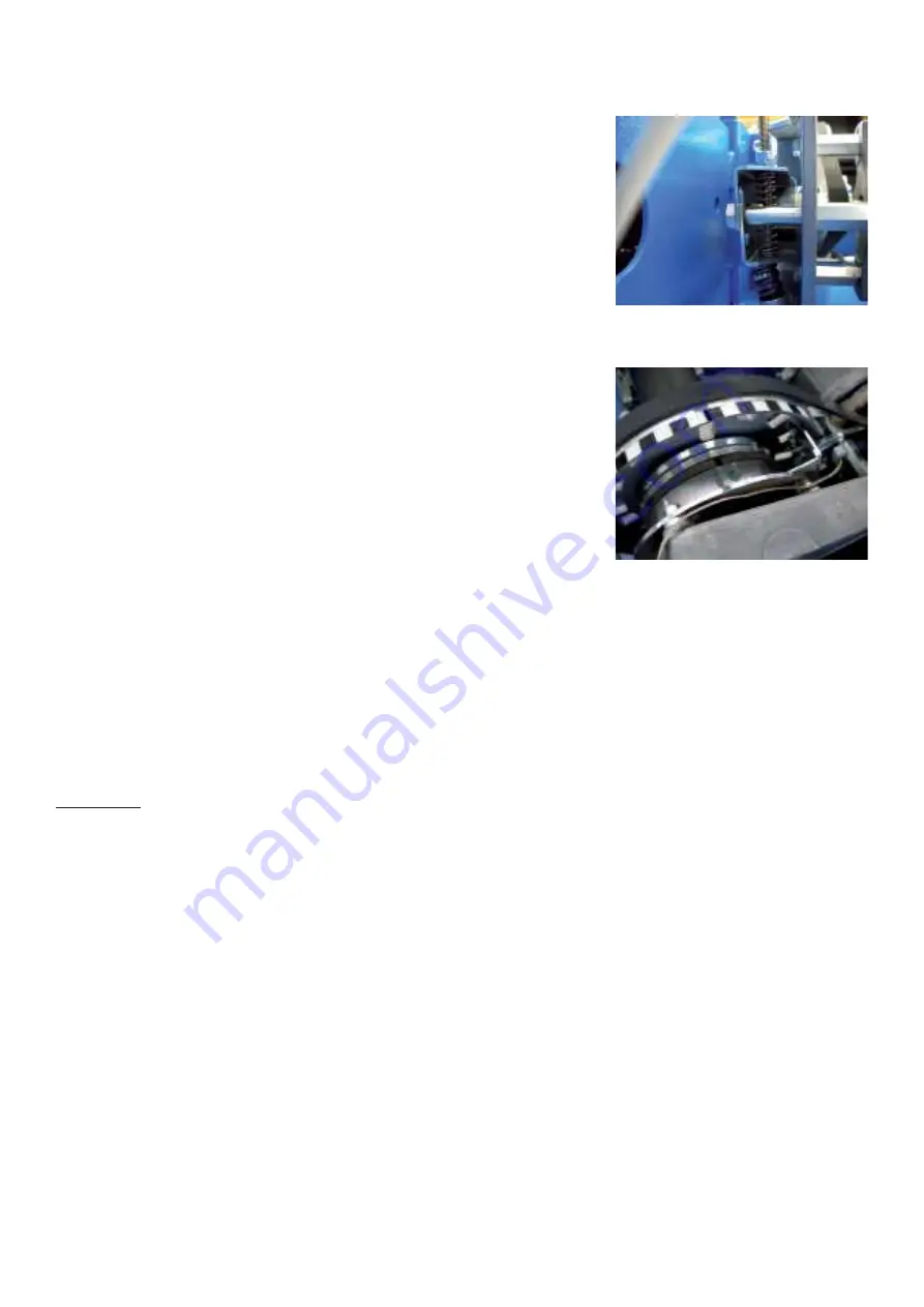
The mechanical brake is pedal operated and acts on the motor pulley.
There is no electrical interlock. The motion of the pedal, conveyed via
Bowden cable, pulls together the two brake levers with glued on brake pads.
The front fastening screw of the motor serves as the lever pivot.
The locknuts (10-mm across the fl ats) at the end of the Bowden cable are
adjusted for 1mm / 0.04nch travel before the levers, moved together by hand,
hit the rear fastening screw of the motor.
3.17 THE ELECTROMAGNETIC BRAKE
The electromagnetic brake is used on power clamp balancers. Once the balancer
reaches a low RPM the Main Processor looks for the outside weight position.
Once this location is known the Processor sends a command to turn on the
Electromagnetic brake. The PCB sends 150VDC to the Electromagnetic brake on
the motor stopping the tire and wheel assembly at TDC for the outside weight
location. Once the weight is applied the operator can then press the “START”
the wheel, this sends the command to the Main Processor which in turns sends
a command to rotate the motor. The Main Processor then sends a command
to engage the Electromagnetic brake stopping the tire and wheel assembly
at TDC for the inside weight location.
Ø
Big solenoid brake with a brake power of 30Nm / 6.74lbsft acting on the main
shaft. Used with the power-clamping device only.
Ø
Small solenoid brake of three Nm braking torque, acting on the motor pulley is used as shaft-lock and position
brake e.g. for the “sticky on top” function.
The brake comprises of a ring shaped stator with the winding behind the brake lining and the brake disc fastened
axially movable to the hub by an annular leaf spring. Without power, there is no friction at all, since the brake disc
is separated from the stator by an air gap. With current applied to the solenoid, the disc is pulled to the stator by
magnetic force. With rotary motion of the hub, friction will develop between the brake disc and both the lining and the
steel body of the stator (hybrid friction).
CAUTION!
There is line voltage at the brake solenoids.
3.18 POWER CLAMPING DEVICE
Description:
The power-clamping device, moving the tie rod comprises of the following components:
a) The axially bored main shaft with the tapered end, the MZV-
p
adaptor is fi tted on and tightened
axially by two hexagon screws (13 mm across the fl ats) to the to bayonet disc.
b) The tie-rod with a spline shaft as part of it, so axial moveable in the bore of the main shaft. A short piece left-handed
thread of 8-mm pitch is fi tted to a spring, loaded to the left-hand end of the tie-rod.
c) The big pulley at the left-hand end of the main shaft supported by ball bearings.
d) The clamping nut of 8-mm pitch is fl ange-mounted to the big pulley with the thread of the tie-rod engaged in it.
e) The incremental encoder B9 to determine tie rod travel and angular position of the drive disc.
f) Solenoid brake. The stator is fastened to the welded part and the brake disc to the main shaft.
g) The pedal unit with two micro-switches S4 and S5 for actuating clamping action and the main shaft
lock.
The Power Interface section of the IBP provides the following functions:
Ø
The high voltage brake driver with brake ammeter
Ø
The AC controller for various motor torque
Ø
The motor ammeter Inputs for polling the pedal micro switches and the proximity detector.
SM HOF GEODYNA 7600 Rel.D


