HYBRID/TROUBLE SHOOTING
3–684
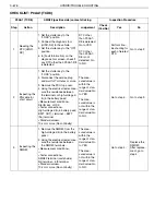
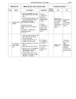
CHECKLIST: P0AA4 (TCD9)
P0AA4 (TCD9)
SMR#1 and 3 (negative side) contact sticking
Inspection Procedure
Step
Action
Description
Judgement
Check
(Yes/No)
Yes
No
1
Reading the
DTC [HINO-
DX]
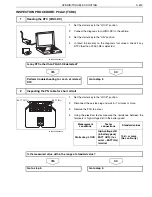
1. Set the starter key to the
"LOCK" position.
2. Connect the diagnosis tool
(HINO-DX) to the vehicle.
3. Set the starter key to the "ON"
position.
4. In [Fault Information] on the
diagnosis tool screen, check if
any DTC other than P0AA4-D9
is detected:
DTC other
than P0AA4-
D9 is detected:
Go to YES.
DTC other
than P0AA4-
D9 is not
detected: Go
to NO.
Perform trou-
bleshooting for
each of related
DTC.
Go to step 2.
2
Inspecting the
system main
resistor
1. Set the starter key to the
"LOCK" position.
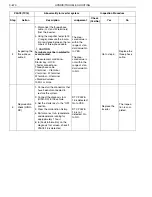
2. Disconnect the service plug
and wait for 7 minutes or more.
3. Remove the PCU top cover.
4. Remove the system main resis-
tor.
5. Using the electrical tester, mea-
sure the resistance between
the terminals of system main
resistor.
<Measurement conditions>
—
<Tester connections>
Between the terminals of system
main resistor
<Standard values>
29.5
–
30.5
The mea-
sured value is
within the
range of stan-
dard value: Go
to YES.
The mea-
sured value is
not within the
range of stan-
dard value: Go
to NO.
Go to step 3.
Replace the
system main
resistor.
After replace-
ment, go to
step 3.
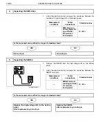
3
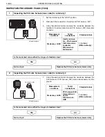
Inspecting the
PN cable for
short circuit
1. Install the system main resistor.
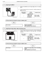
2. Using the electrical tester, mea-
sure the resistance between
the terminals of high-voltage J/
B (in the battery pack)
<Measurement conditions>
—
<Tester connections>
High-voltage J/B (in battery pack)
BATT OUT(-) terminal
–
BATT
IN(-) terminal
<Standard values>
29.5
–
30.5
The mea-
sured value is
within the
range of stan-
dard value: Go
to YES.
The mea-
sured value is
not within the
range of stan-
dard value: Go
to NO.
Go to step 4.
Go to step 5.

