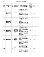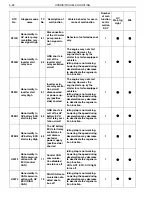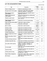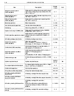
HYBRID/TROUBLE SHOOTING
3–40
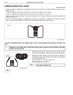
(2) CHART FOR INSPECTION OF THE SIGNAL LINE AT THE PCU UPPER SIDE WIRE HARNESS FOR SHORT CIR-
CUIT
1.
Set the starter key to the "LOCK" position.
2.
Disconnect the following connectors.
•
PCU harness 16-pin connector
•
HV battery cooling fan connector
•
Battery ECU (CAN) connector
3.
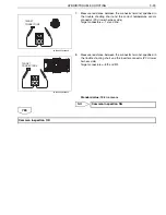
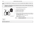
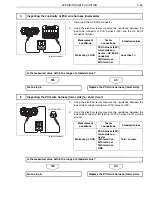
Measure resistance between the connector terminal specified in
the trouble shooting chart and the PCU harness 16-pin connector
(PCU upper harness side).
Target connectors
1st to 16th (except 10th)
Standard value: 10 k
or more
NO
YES
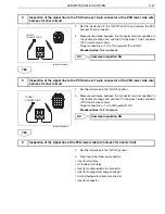
1
Inspection of the signal line to the PCU harness 16-pin connector at the PCU upper side wire
harness for short circuit
TARGET
CONNECTORS
SHTS03ZZZ0300030
Common inspection NG
Common inspection OK

