HYBRID/TROUBLE SHOOTING
3–278
1.
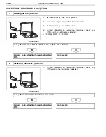
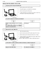
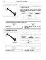
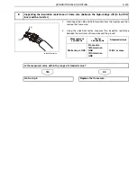
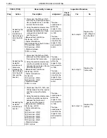
Disconnect the 9th and 10th terminals from the high-voltage J/B
(in the ECU box), and then remove the frame wire.
2.
Using the electrical tester, measure the insulation resistance
between the terminals of frame wire and the ground.
NO
YES
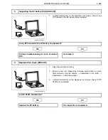
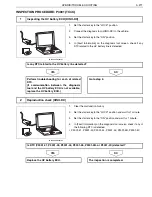
1.
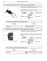
Disconnect the 13th and 14th terminals from the high-voltage J/B
(in the ECU box), and then remove the frame wire.
2.
Using the electrical tester, measure the insulation resistance
between the terminals of high-voltage J/B (in the ECU box) and
the ground.
NO
YES
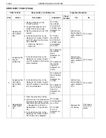
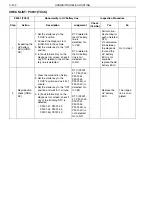
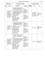
6
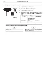
Inspecting the insulation resistance of frame wire (to the high-voltage J/B)
[9]
[10]
SHTS03ZZZ0300188
Measurement
conditions
Tester
connections
Standard values
Starter key: LOCK
Frame wire
9th terminal
–
GND
10th terminal
–
GND
10 M
or more
Is the measured value within the range of standard value?
Go to step 7.
Replace the frame wire.
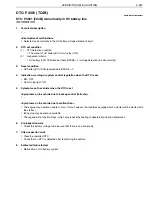
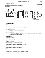
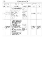
7
Inspecting the insulation resistance of high-voltage J/B (in the ECU box)
DDC(-)[12]
DDC(+)[11]
SHTS03ZZZ0300189
Measurement
conditions
Tester
connections
Standard values
Starter key: LOCK
High-voltage J/B
(in the ECU box)
11th terminal
–
GND
12th terminal
–
GND
10 M
or more
Is the measured value within the range of standard value?
Go to step 8.
Replace the high-voltage J/B (in the ECU
box).

