HYBRID/TROUBLE SHOOTING
3–415
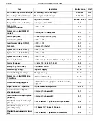
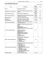
FREEZE FRAME DATA LIST
EN01H03ZZZ030602004002
Item
Description
Display range
Unit
TC No.
Detailed code of DTC No.
00 - $FF (Hex)
—
Specified value of motor torque
Represents a torque command value to the
inverter.
-32,768 - 32,767
Nm
Actual motor torque value
Represents the motor output torque.
-32,768 - 32,767
Nm
Effective motor torque value
Effective motor torque value (Torque calculated
from actual current id, iq)
-32,768 - 32,767
Nm
Motor revolution
Represents the motor revolution.
0 - 4,000
r/min
DC voltage
Represents the inverter DC voltage.
0 - 600
V
Motor temperature
Represents the motor temperature.
0 - 200
C
Inverter internal temperature
Represents the main circuit element temperature
(INV temperature).
0 - 200
C
HV control mode information
Represents the operating condition of the HV
system.
OFF = 0
Engine startup = 1
At acceleration by motor = 2
Deceleration by motor + retarder or foot brake = 3
Deceleration by motor = 4
HV battery charging = 5
Engine stop = 6
Forced HV battery charging = 7
At manufacturing inspection = 8
At EV = 9
At gear shifting = 10
Not defined = 11 to 15
0 - 15
—
Motor control mode information
Indicates a motor operating state.
0 = Shutdown
1 = Torque control
2 = Discharge preparation
3 = Discharge
4 = Revolution control
0 - 15
—
Inverter control mode informa-
tion
Represents the operation status of the inverter.
0 = Initialization
1 = Pre-charge standby
2 = At pre-charge
3 = At normal operation
4 = Waiting for discharge permission
5 = At SMR off
6 = At discharge command
7 = At discharge completion
8 = At emergency start (pre-charge)
9 = At emergency start
0 - 15
—
HV battery voltage
Indicates HV battery voltage.
0 - 600
V
Difference voltage not satisfied
Represents the unsatisfied difference voltage
count.
0 - 255
Times
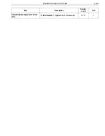
Motor current effective value
(RMS)
Motor current RMS
-3,276.8 - 3,276.7
A


