HYBRID/TROUBLE SHOOTING
3–64
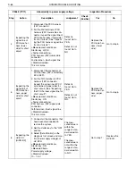
4
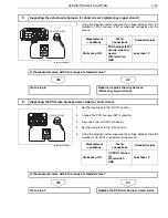
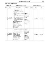
Inspecting the
signal line of
PCU wire har-
ness (lower
side) for short
circuit
1. Disconnect the PCU harness
(24P) connector.
2. For the 2nd terminal of PCU
harness (24P) lower-side con-
nector, inspect the signal line of
PCU wire harness (lower side)
for short circuit. (See "Inspect-
ing the PCU harness signal line
for short circuit.")
<Measurement conditions>
Starter key: LOCK
<Tester connections>
PCU harness (24P) lower-side
connector
2nd terminal
–
Each signal line
<Standard values>
10 k
or more
Defect is
found: Go to
YES.
Defect is not
found: Go to
NO.
Replace the
PCU wire har-
ness (lower
side).
Go to step 5.
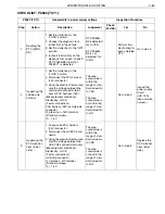
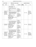
5
Inspecting the
signal line of
PCU wire har-
ness (upper
side) for short
circuit
1. Disconnect the connectors of
PCU harness (16P) and battery
ECU (26P).
2. For the 13th terminal of PCU
harness (16P) connector,
inspect the signal line of PCU
wire harness (upper side) for
short circuit. (See "Inspecting
the PCU harness signal line for
short circuit.")
<Measurement conditions>
Starter key: ON
<Tester connections>
PCU harness (16P) upper-side
connector
16th terminal
–
Each signal line
<Standard values>
10 k
or more
Defect is
found: Go to
YES.
Defect is not
found: Go to
NO.
Replace the
PCU wire har-
ness (upper
side).
Go to step 6.
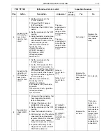
6
Inspecting the
HV ECU
[HINO-DX]
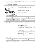
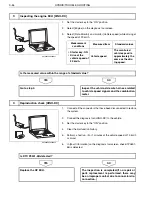
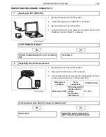
1. Connect all the connectors that
have been disconnected to
restore the system.
2. Set the starter key to the "ON"
position.
3. Select [Data Monitor] on the
diagnosis tool screen and mon-
itor [Power supply voltage] of
HV ECU.
<Measurement conditions>
Starter key: ON
<Measured item>
Power supply voltage
<Standard values>
10
–
16 V
The mea-
sured value is
within the
range of stan-
dard value: Go
to YES.
The mea-
sured value is
not within the
range of stan-
dard value: Go
to NO.
Go to step 7.
Replace the
HV ECU.
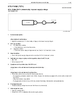
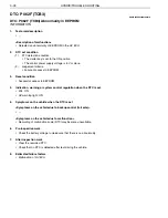
P0562 (TC71)
Abnormality in power supply voltage
Inspection Procedure
Step
Action
Description
Judgement
Check
(Yes/No)
Yes
No


