HYBRID/TROUBLE SHOOTING
3–36
COMMON INSPECTION CHART
EN01H03ZZZ030602003004
•
If common inspection requirements are described in the trouble shooting chart, conduct inspection using the common
inspection chart.
.
1. Chart for inspection of the signal line at the PCU lower side wire harness for short circuit
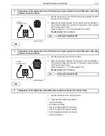
2. Chart for inspection of the signal line at the PCU upper side wire harness for short circuit
•
Target connector terminals described in the common inspection chart represent terminals of connectors specified in the
trouble shooting chart.
•
As shown in the following figure, if measurement of resistance of the terminal is required on the common inspection
chart, do not determine the terminal as "NG" and proceed to measurement of the next terminal.
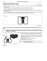
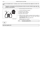
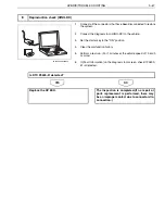
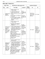
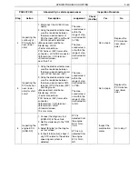
(1) CHART FOR INSPECTION OF THE SIGNAL LINE AT THE PCU LOWER SIDE WIRE HARNESS FOR SHORT CIR-
CUIT
1.
Set the starter key to the "LOCK" position and remove the PCU
harness 24-pin connector and the PCU harness 16-pin connector.
2.
Measure resistance between the connector terminal specified in
the trouble shooting chart and the PCU harness 24-pin connector
(PCU lower harness side).
Target connectors
1st to 24th (except 17th)
Standard value: 10 k
or more
NO
YES
1
Inspection of the signal line to the PCU harness 24-pin connector at the PCU lower side wire
harness for short circuit
(Example)
SHTS03ZZZ0300020
TARGET
CONNECTORS
SHTS03ZZZ0300021
Common inspection NG

