


GE Healthcare
Direction 5743854-1EN, Revision 1 Optima XR642/XR648 Pre-Installation
Page 98
Section 2.0 - Electrical Requirements
2.2
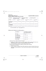
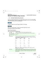
System Wire Sizes & kVA Load Characteristics
• Calculations based upon nominal voltage, wire size in AWG. To convert to mm2, refer to Table 5-2.
• Recommended feeder sizes from distribution transformer to the power cabinet.
• Neutral must be terminated inside the main disconnect panel and not at any GE cabinet.
• The grounding conductor will be of same size as the feeder wires. This ground will run from equipment back to the
facility power source / main grounding point and always travel in the same conduit with the feeders and neutral.
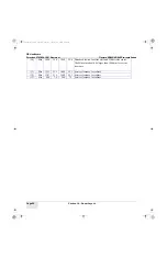
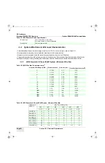
2.2.1
JEDI Generator 3-Phase 50 kW System - Minimum Wire Size
HV cable type
USA: 22mm DSI (<= 165 pF/m)
HV cable connector = Federal standard
Ground Wire
Same as power cable
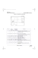
Table 5-2 AWG Wire Size Conversion to mm
2
American Wire Gauge (AWG)
Diameter (Inches)
Diameter (mm)
Cross Sectional Area (
mm
2
)
6
0.1620
4.11
13.30
5
0.1819
4.62
16.77
4
0.2043
5.19
21.15
3
0.2294
5.83
26.65
2
0.2576
6.54
33.61
1
0.2893
7.35
42.39
1/0
0.3249
8.25
53.46
2/0
0.3648
9.27
67.40
3/0
0.4096
10.40
84.97
4/0
0.46
11.68
107.16
250M
0.575
14.6
126.68
300M
0.630
16.0
152.0
350M
0.681
17.3
177.35
400M
0.728
18.49
202.68
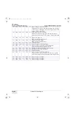
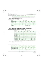
Table 5-3 JEDI Generator 3-Phase 50 kW System - Minimum Wire Size
WIRE RUN
LENGTH
INPUT VOLTAGE (VAC)
380
400
420
440
460
480
+/- 10%
+/- 10%
+/- 10%
+/- 10%
+/- 10%
+/- 10%
15m (50 ft.)
*6
*6
*6
*6
*6
*6
30m (100 ft.)
5
5
*6
*6
*6
*6
46m (150 ft.)
4
4
4
4
4
4
61m (200 ft.)
3
4
4
4
4
4
77 m (250 ft)
2
2
2
3
3
4
92 m (300 ft)
1/0
1
1
2
2
2
107m ( 350ft)
2/0
2/0
1/0
1
1
1
122m (400 ft)
3/0
2/0
2/0
1/0
1/0
1/0
Table 5-1 JEDI Generator Power Specifications
Pre-Install.book Page 98 Tuesday, January 30, 2018 2:36 PM


