GE Healthcare
Direction 5743854-1EN, Revision 1 Optima XR642/XR648 Pre-Installation
Page 100
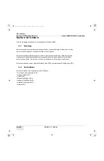
Section 2.0 - Electrical Requirements
2.2.5
JEDI Generator 3-Phase 80 kW and System - Minimum Wire Size
2.2.6
kVA Load Characteristics 80KW
2.3
Recommended Wall “Circuit-Breaker” Ratings
2.4
Wiring Electrical Power and Disconnects
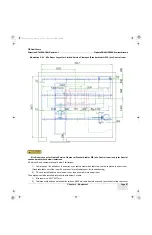
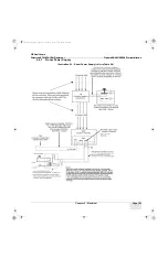
This section provides additional data regarding power circuits the customer must provide, and internal electrical circuits
necessary to supply the correct power to the system. Illustration 5-1 shows the room power supply installed.
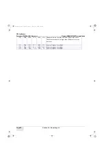
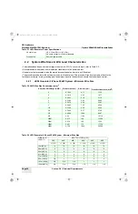
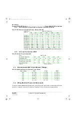
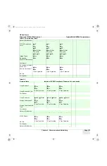
Table 5-7 JEDI Generator 3-Phase 80 kW System - Minimum Wire Size
WIRE RUN
LENGTH
INPUT VOLTAGE (VAC)
380
400
420
440
460
480
+/- 10%
+/- 10%
+/- 10%
+/- 10%
+/- 10%
+/- 10%
15m (50 ft.)
*2
*2
*2
*2
*2
*2
30m (100 ft.)
*2
*2
*2
*2
*2
*2
46m (150 ft.)
1/0
1
1
*2
*2
*2
61m (200 ft.)
2/0
2/0
1/0
1/0
1
1
77 m (250 ft)
3/0
3/0
2/0
2/0
1/0
1/0
92 m (300 ft)
4/0
4/0
3/0
3/0
2/0
2/0
107m ( 350ft) 300M
250M
4/0
4/0
3/0
3/0
122m (400 ft) 350M
300M
250M
4/0
4/0
3/0
138m (450 ft) 400M
350M
300M
250M
250M
4.0
* minimum wire size for circuit breaker, based on recommended over current protection.
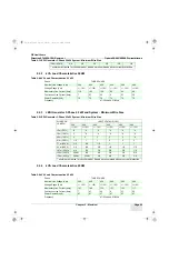
Table 5-8 kVA Load Characteristics 80 kW
Phase
THREE PHASE
Nominal Line Voltage (Vac)
380
400
420
440
460
480
Voltage Range (Vac)
+/- 10%
+/- 10%
+/- 10%
+/- 10%
+/- 10%
+/- 10%
Momentary Line Current (Amp)
190
180
170
163
156
150
Continuous Line Current (Amp)
7
6.7
6.2
6
5.7
5.5
Power Demand (kVA)
125
125
125
125
125
125
Frequency
47/53Hz and 57/63Hz
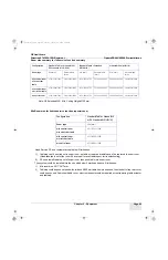
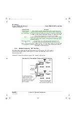
Table 5-9 Wall Breaker Parameter (Theoretical Current Values)
Power / Voltage
50 kW
65 kW
80 kW
380 V
55 A / 600 V
74 A / 600 V
95 A / 600 V
400 V
52 A / 600 V
70 A / 600 V
90 A / 600 V
415 V
50 A/ 600 V
67 A / 600 V
85 A / 600 V
440 V
47 A / 600 V
64 A / 600 V
82 A / 600 V
460 V
45 A/ 600 V
61 A / 600 V
78 A / 600 V
480 V
43 A / 600 V
59A / 600 V
75 A / 600 V
Pre-Install.book Page 100 Tuesday, January 30, 2018 2:36 PM

