


GE Healthcare
Direction 5743854-1EN, Revision 1 Optima XR642/XR648 Pre-Installation
Page 102
Section 2.0 - Electrical Requirements
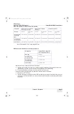
Legend for Illustration 5-1
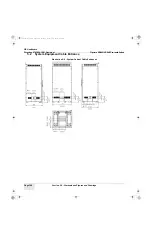
2.4.2
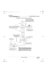
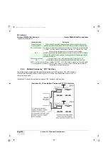
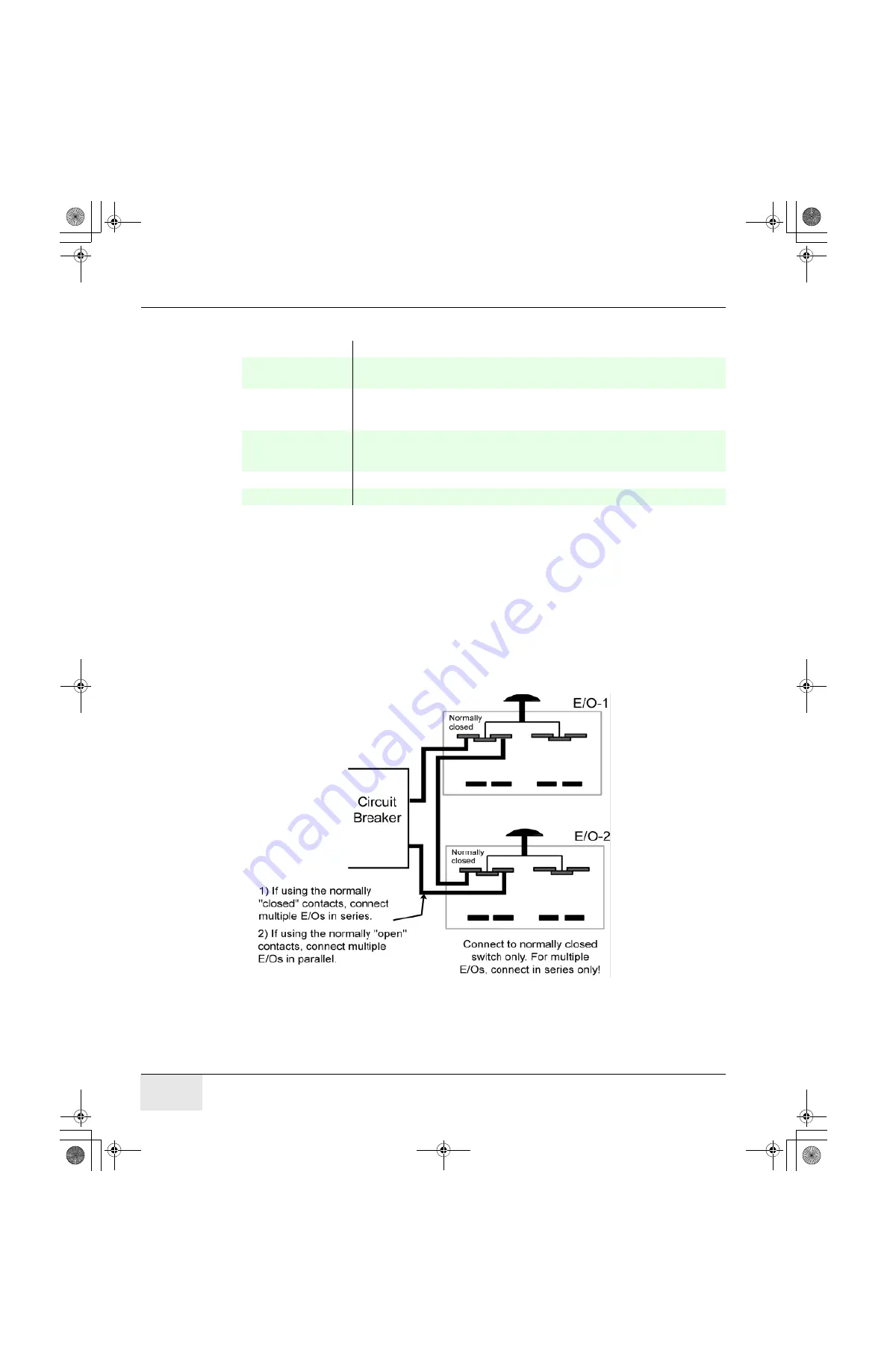
Multiple Emergency “OFF” Switches
The facility designer determines the quantity and locations of the Emergency OFF (E/O) switches.
GE recommends placing at least one Emergency OFF switch near the doorway of every room in
the system scan suite.
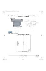
Illustration 5-2 shows how multiple Emergency “OFF” switches could be wired.
Illustration 5-2 : Wiring Multiple “Emergency OFF” (E/O) Switches
United States Key
Description
Feeder Wires and
Grounding Cable
Feeder wire and grounding cable supplied by the customer. Wires are to be
provided by customer with inlet to SKL with 2 meters for internal cabinet routing).
E/O (see Note below) Emergency Off switch located near room access door. The switch is supplied by the
Hospital. The recommended distance above the floor is 1.5 meters. Use only a
multi-conductor, shielded cable to connect to System Cabinet.
XRL
Yellow X-ray emission indicator lamp above the room access door. 220 V in Europe/
120 V in USA with 25 W max. bulb (per local regulations). Wires and light fixtures
supplied by customer.
DLK (see Note below)
Open-door detector (per local regulations). SKL provides 24 VDC.
CB
Circuit breaker with remote trip (shunt) capabilities supplied by customer.
NOTE: Use only a multi-conductor, shielded, PVC/PVC, UL TYPE CM cable, Alpha wire. The cable shield
must be grounded at both ends.with the system cabinet grounding, avoid make wireless transmission
unintelligible by causing interference.
Pre-Install.book Page 102 Tuesday, January 30, 2018 2:36 PM


