3-2
745 Transformer Management Relay
GE Power Management
3.1 DRAWOUT CASE
3 INSTALLATION
3
3.1.3 CASE MOUNTING
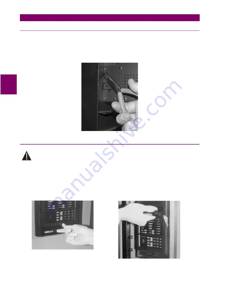
Before mounting the SR unit in the supporting panel, remove the relay portion from its case, as described in
the next section. From the front of the panel, slide the empty case into the cutout. To ensure the front bezel sits
flush with the panel, apply pressure to the bezel’s front while bending the retaining tabs 90°. These tabs are
located on the sides and bottom of the case and appear as shown in the illustration. After bending all tabs, the
case will be securely mounted so that its relay can be inserted. The SR unit is now ready for panel wiring.
Figure 3–3: CASE MOUNTING
3.1.4 UNIT WITHDRAWAL AND INSERTION
TURN OFF CONTROL POWER BEFORE DRAWING OUT OR RE-INSERTING THE RELAY TO
PREVENT MALOPERATION!
a) RELAY WITHDRAWAL
1.
Open the door by pulling from the center of its right side. It will rotate to the left about its hinges.
2.
Press upward on the locking latch, which is located below the handle, and hold in its raised position. The
tip of a small screwdriver may prove helpful in this operation.
3.
With the latch raised, pull the center of the handle outward. Once disengaged, continue rotating the handle
up to the stop position.
CAUTION
Press Latch Up and Pull Handle
Rotate Handle to Stop Position
Содержание 745 TRANSFORMER MANAGEMENT RELAY
Страница 30: ...2 8 745 Transformer Management Relay GE Power Management 2 3 SECURITY 2 GETTING STARTED 2 ...
Страница 150: ...5 100 745 Transformer Management Relay GE Power Management 5 10 INVERSE VOLTS PER HERTZ CURVES 5 SETPOINTS 5 ...
Страница 210: ...7 36 745 Transformer Management Relay GE Power Management 7 2 BLOCK DIAGRAMS 7 SCHEME LOGIC 7 ...
Страница 322: ...9 12 745 Transformer Management Relay GE Power Management 9 3 USING 745PC 9 745 PC SOFTWARE 9 ...
Страница 392: ...11 24 745 Transformer Management Relay GE Power Management 11 1 COMMISSIONING SUMMARY 11 SETPOINT TABLES 11 ...
Страница 396: ...A 4 745 Transformer Management Relay GE Power Management A 1 FIGURES AND TABLES APPENDIXA A ...
Страница 398: ...B 2 745 Transformer Management Relay GE Power Management B 1 EU DECLARATION OF CONFORMITY APPENDIXB B ...
Страница 400: ...C 2 745 Transformer Management Relay GE Power Management C 1 WARRANTY INFORMATION APPENDIXC C ...
Страница 406: ...vi 745 Transformer Management Relay GE Power Management ...
Страница 407: ...GE Power Management 745 Transformer Management Relay NOTES ...


