

SS1807-N002
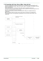
Installation
-
37/68
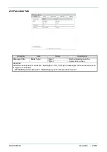
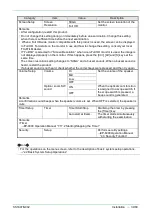
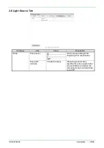
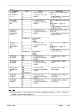
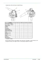
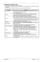
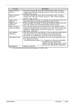
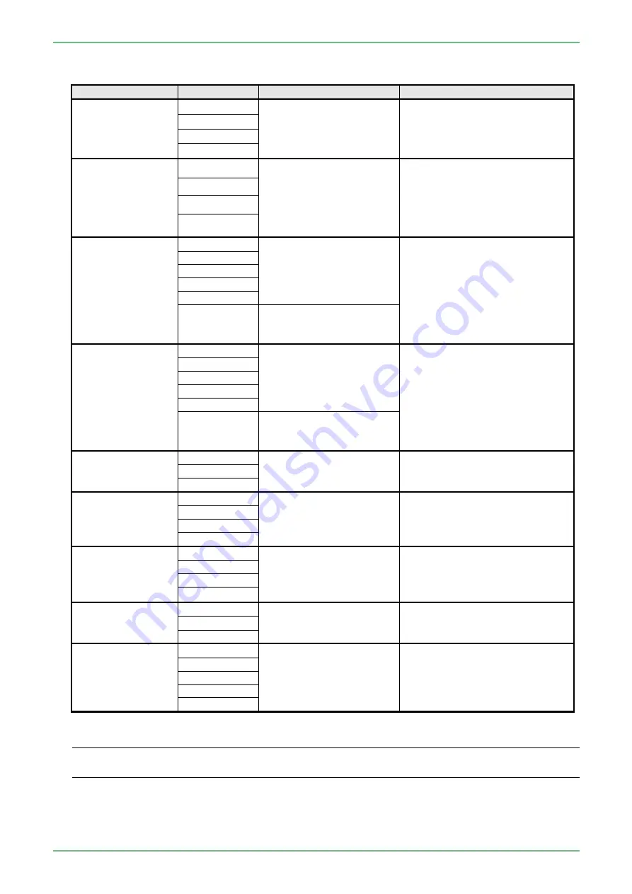
Table 2
Category
Item
Value
Description
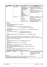
700 System
Freeze Mode
F/T F+T
1
→“<Functions to be
assigned to the scope
switch>”
The freeze mode “F/T” or “F+T”
can be set.
→“• Assignments of 700 System
(4-Switch) Scope”
2
3
4
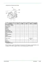
700 System
Freeze Mode
FRZ
1
→“<Functions to be
assigned to the scope
switch>”
Only the freeze mode “FRZ” can
be set.
Assignment of “Trigger” is
essential.
→“• Assignments of 700 System
(4-Switch) Scope”
2
3
4
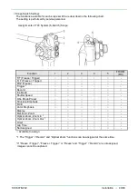
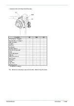
700/Z System
Opt. Zoom
Freeze Mode
F/T F+T
1
→“<Functions to be
assigned to the scope
switch>”
The freeze mode “F/T” or “F+T”
can be set.
→“• Assignments of 700 System
(5-Switch) Scope”
2
3
4
5
FR+OM
(
RC
)
Not Assigned
Trigger
Record
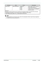
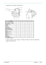
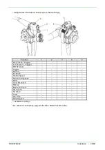
700/Z System
Opt. Zoom
Freeze Mode
FRZ
1
→“<Functions to be
assigned to the scope
switch>”
Only the freeze mode “FRZ” can
be set.
Assignment of “Trigger” is
essential.
→“• Assignments of 700 System
(5-Switch) Scope”
2
3
4
5
FR+OM
(
RC
)
Not Assigned
Trigger
Record
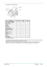
500 System
600 System
FR
→“<Functions to be
assigned to the scope
switch>”
→“• Assignments of Normal
Scope”
MM
RC
500 System
600 System
1
→“<Functions to be
assigned to the scope
switch>”
→“• Assignments of Normal
Scope”
2
3
4
600 System Opt.
Zoom with SP
SW
FR
→“<Functions to be
assigned to the scope
switch>”
→“• Assignments of Optical
Zoom Scope”
MM
SP
FR+OM
(
RC
)
500 System
Ultrasonic
FR
→“<Functions to be
assigned to the scope
switch>”
→“• Assignments of Ultrasonic
Endoscope”
MM
RC
500 System
Ultrasonic
1
→“<Functions to be
assigned to the scope
switch>”
→“• Assignments of Ultrasonic
Endoscope”
2
3
4
5
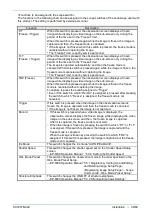
◆
Note
◆
・
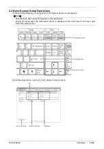
For the operations on the menu screen, refer to the description of basic system setup operations.
→
“2.2 Basic System Setup Operations”
Содержание EP-6000
Страница 1: ...Processor EP 6000 FV693A Service Manual SR1807 N002 Ver 1 Oct 2018 ...
Страница 5: ...SS1807 N002 General Table of Contents 1 1 General Table of Contents ...
Страница 13: ...SS1807 N002 Caution in Safety 1 12 Caution in Safety ...
Страница 18: ...SS1807 N002 Caution in Safety 6 12 2 Label 2 1 EP 6000 Labeling Layout FV693A 2 1 1 Labeling chart D B A C ...
Страница 25: ...SS1807 N002 Product Specifications 1 11 Product Specifications ...
Страница 36: ...SS1807 N002 Instruction of System 1 106 Instruction of System ...
Страница 52: ...SS1807 N002 Instruction of System 17 106 In the case of Normal mode In the case of BLI BLI bright or LCI ...
Страница 131: ...SS1807 N002 Instruction of System 96 106 9 EP 6000 Description of Configuration 9 1 Block Diagram ...
Страница 133: ...SS1807 N002 Instruction of System 98 106 ELC PCB Patient PCB APC PCB APC PCB APC PCB DC Pump ...
Страница 139: ...SS1807 N002 Instruction of System 104 106 9 4 Outline of PCB roles ...
Страница 142: ...SS1807 N002 Failure Analysis 1 64 Failure Analysis ...
Страница 206: ...SS1807 N002 Checkup Replacement and Adjustment 1 137 Checkup Replacement and Adjustment ...
Страница 343: ...SS1807 N002 Service Parts List 1 19 Service Parts List ...
Страница 348: ...SS1807 N002 Service Parts List 6 19 6 13 13 16 18 17 17 6 18 14 15 6 9 10 6 12 7 6 11 8 6 5 1 4 3 2 ...
Страница 350: ...SS1807 N002 Service Parts List 8 19 13 12 14 11 14 17 7 7 2 6 15 7 2 3 4 1 5 2 10 9 17 7 7 8 18 12 13 16 ...
Страница 352: ...SS1807 N002 Service Parts List 10 19 2 2 2 4 1 3 3 2 3 3 6 5 ...
Страница 356: ...SS1807 N002 Service Parts List 14 19 1 3 3 4 1 2 1 3 X 4 1 3 3 4 3 3 ...
Страница 358: ...SS1807 N002 Service Parts List 16 19 3 1 2 1 ...
Страница 360: ...SS1807 N002 Service Parts List 18 19 Fig 09 5 4 2 3 1 ...
Страница 362: ...SS1807 N002 Periodical Maintenance 1 15 Periodical Maintenance ...
Страница 377: ...SS1807 N002 Installation 1 68 Installation ...
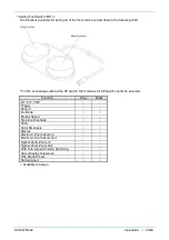
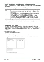
Страница 381: ...SS1807 N002 Installation 5 68 1 2 Installation onto the Cart Standard System Installation Example ...
Страница 445: ...SS1807 N002 ...


