SS1807-N002
Failure Analysi
-
3/64
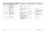
2. Error Message
Explanation of code displayed on the screen together with message
(Please write down the failure condition and the display code No. in case of request for repair)
Display
error
code
Classification
level
Display message
(occurrence, response)
Display message
(guidance to
error)
Estimated cause
Trigger of message display
Service response
0
Information
Definition of code without
error. Not displayed.
1
Warning
Could not connect to the
network.
Cause: Network
setting is incorrect
or network is in
abnormal state.
Although trying to use the
network function, PING was not
inserted up to the gateway
(router)
At the time of connection
checkup at the start-up,
At the time of network connection
checkup
(when access to network is
required)
(1) Check if the network setting
of the system environmental
setting is correct.
(2) Check if there are any
abnormalities in cable connection
to the gateway.
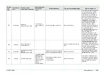
2
Information
Configuration file will be
saved in External
Memory.
OK?
“Configuration file saving” was
selected at the backup of the
service menu.
Same as on the left
Dialog selection→
3
Information
Saving configuration file
in External Memory.
Please wait for a while.
⇒
Do not remove
External Memory
while saving data.
“Yes” was selected at the above
dialog.
Same as on the left
Wait till saving is finished.
If the message does not
disappear after waiting a while, In
case of repetitive errors after
that, replace External memory,
USB PCB and the Harness
(Main-USB).
4
Information
Saving configuration file is
completed.
Saving configuration file was
completed.
Same as on the left
Press any key to close the
dialog.
5
Warning
Saving configuration file
has failed.
Check External Memory.
Saving configuration file failed.
Same as on the left
After the contents of the inserted
External memory have been
backed up in Windows PC, etc.,
insert External memory again
and save the file after External
memory has been
physical-formatted instead of
being quick-formatted.
In case of repetitive errors after
that, replace External memory,
USB PCB and the Harness
(Main-USB).
6
Information
Configuration file will be
loaded from External
Memory.
After loading, system
restart is required. OK?
“Configuration file loading” was
selected at the backup of the
service menu.
Same as on the left
Dialog selection→
Содержание EP-6000
Страница 1: ...Processor EP 6000 FV693A Service Manual SR1807 N002 Ver 1 Oct 2018 ...
Страница 5: ...SS1807 N002 General Table of Contents 1 1 General Table of Contents ...
Страница 13: ...SS1807 N002 Caution in Safety 1 12 Caution in Safety ...
Страница 18: ...SS1807 N002 Caution in Safety 6 12 2 Label 2 1 EP 6000 Labeling Layout FV693A 2 1 1 Labeling chart D B A C ...
Страница 25: ...SS1807 N002 Product Specifications 1 11 Product Specifications ...
Страница 36: ...SS1807 N002 Instruction of System 1 106 Instruction of System ...
Страница 52: ...SS1807 N002 Instruction of System 17 106 In the case of Normal mode In the case of BLI BLI bright or LCI ...
Страница 131: ...SS1807 N002 Instruction of System 96 106 9 EP 6000 Description of Configuration 9 1 Block Diagram ...
Страница 133: ...SS1807 N002 Instruction of System 98 106 ELC PCB Patient PCB APC PCB APC PCB APC PCB DC Pump ...
Страница 139: ...SS1807 N002 Instruction of System 104 106 9 4 Outline of PCB roles ...
Страница 142: ...SS1807 N002 Failure Analysis 1 64 Failure Analysis ...
Страница 206: ...SS1807 N002 Checkup Replacement and Adjustment 1 137 Checkup Replacement and Adjustment ...
Страница 343: ...SS1807 N002 Service Parts List 1 19 Service Parts List ...
Страница 348: ...SS1807 N002 Service Parts List 6 19 6 13 13 16 18 17 17 6 18 14 15 6 9 10 6 12 7 6 11 8 6 5 1 4 3 2 ...
Страница 350: ...SS1807 N002 Service Parts List 8 19 13 12 14 11 14 17 7 7 2 6 15 7 2 3 4 1 5 2 10 9 17 7 7 8 18 12 13 16 ...
Страница 352: ...SS1807 N002 Service Parts List 10 19 2 2 2 4 1 3 3 2 3 3 6 5 ...
Страница 356: ...SS1807 N002 Service Parts List 14 19 1 3 3 4 1 2 1 3 X 4 1 3 3 4 3 3 ...
Страница 358: ...SS1807 N002 Service Parts List 16 19 3 1 2 1 ...
Страница 360: ...SS1807 N002 Service Parts List 18 19 Fig 09 5 4 2 3 1 ...
Страница 362: ...SS1807 N002 Periodical Maintenance 1 15 Periodical Maintenance ...
Страница 377: ...SS1807 N002 Installation 1 68 Installation ...
Страница 381: ...SS1807 N002 Installation 5 68 1 2 Installation onto the Cart Standard System Installation Example ...
Страница 445: ...SS1807 N002 ...


