SS1807-N002
Failure Analysi
-
39/64
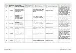
Display
error
code
Classification
level
Display message
(occurrence, response)
Display message
(guidance to
error)
Estimated cause
Trigger of message display
Service response
20015
Warning
Connected scope cannot
be used.
A non-compliant scope was
connected and startup or
inspection start was executed
Same as on the left
In case of repetitive failures
applicable scopes, replace the
scope (prototypes or scopes for
overseas may have unexpected
IDs
)
and the patient PCB.
20016
Warning
Scope is turned off.
Execute scope installation
during the standby state.
Performed scope CPU
installation with the scope not
turned ON.
Same as on the left
In case of repetitive failures in
spite of inspectable condition,
replace the patient PCB and the
main PCB..
20017
Warning
The power is turned off
while saving the result of
scope color adjustment.
Execute scope color
adjustment again.
Power turned OFF during writing
in for scope color adjustment.
After the same as on the left,
whenever starting up till the
scope color adjustment results
have been properly saved
In case of repetitive failures even
if scope color adjustment was
tried again, replace the main
PCB.
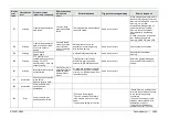
20018
Warning
Examination cannot be
started because two
scopes are inserted.
When the examination button
was pressed, both of the 2
connectors were set.
Same as on the left
In case of repetitive failures even
if the scope is not connected to
both of the 2 connectors, replace
the scope connector and the
patient PCB.
20021
Error
Update of scope CPU
failed.
400-series scopes cannot
be updated.
A scope update was performed
while a 400-series scope was
connected.
Same as on the left
Updating of a 400-series scope is
not possible and must therefore
not be executed.
20022
Warning
Automatic color
adjustment cannot be
executed with this scope.
A 400-series scope with no AWB
support was connected.
When auto color adjustment is
executed while a 400-series
scope with no AWB support is
connected.
In case of repetitive failures in a
scope that supports AWB
execution, replace the patient
PCB and main PCB and inspect
the scope.
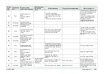
20023
Warning
Unplug and plug back
endoscope, reset the
processor. If the problem
persists, contact your
local FUJIFILM dealer.
Cause:
Initialization of
endoscope failed.
The scope could not be initialized
due to communication noise.
When a system startup or
inspection is started while a
400-series scope is connected.
In case of repetitive failures,
replace the EVE connector, the
scope, and the patient PCB.
20024
Warning
Two scopes are inserted.
End examination and
connect the cap to the
connector not to be used.
A second scope was connected
during inspection.
Same as on the left
In case of repetitive failures in
spite of the second scope not
being connected, replace the
scope connector, the scope, and
the patient PCB.
Содержание EP-6000
Страница 1: ...Processor EP 6000 FV693A Service Manual SR1807 N002 Ver 1 Oct 2018 ...
Страница 5: ...SS1807 N002 General Table of Contents 1 1 General Table of Contents ...
Страница 13: ...SS1807 N002 Caution in Safety 1 12 Caution in Safety ...
Страница 18: ...SS1807 N002 Caution in Safety 6 12 2 Label 2 1 EP 6000 Labeling Layout FV693A 2 1 1 Labeling chart D B A C ...
Страница 25: ...SS1807 N002 Product Specifications 1 11 Product Specifications ...
Страница 36: ...SS1807 N002 Instruction of System 1 106 Instruction of System ...
Страница 52: ...SS1807 N002 Instruction of System 17 106 In the case of Normal mode In the case of BLI BLI bright or LCI ...
Страница 131: ...SS1807 N002 Instruction of System 96 106 9 EP 6000 Description of Configuration 9 1 Block Diagram ...
Страница 133: ...SS1807 N002 Instruction of System 98 106 ELC PCB Patient PCB APC PCB APC PCB APC PCB DC Pump ...
Страница 139: ...SS1807 N002 Instruction of System 104 106 9 4 Outline of PCB roles ...
Страница 142: ...SS1807 N002 Failure Analysis 1 64 Failure Analysis ...
Страница 206: ...SS1807 N002 Checkup Replacement and Adjustment 1 137 Checkup Replacement and Adjustment ...
Страница 343: ...SS1807 N002 Service Parts List 1 19 Service Parts List ...
Страница 348: ...SS1807 N002 Service Parts List 6 19 6 13 13 16 18 17 17 6 18 14 15 6 9 10 6 12 7 6 11 8 6 5 1 4 3 2 ...
Страница 350: ...SS1807 N002 Service Parts List 8 19 13 12 14 11 14 17 7 7 2 6 15 7 2 3 4 1 5 2 10 9 17 7 7 8 18 12 13 16 ...
Страница 352: ...SS1807 N002 Service Parts List 10 19 2 2 2 4 1 3 3 2 3 3 6 5 ...
Страница 356: ...SS1807 N002 Service Parts List 14 19 1 3 3 4 1 2 1 3 X 4 1 3 3 4 3 3 ...
Страница 358: ...SS1807 N002 Service Parts List 16 19 3 1 2 1 ...
Страница 360: ...SS1807 N002 Service Parts List 18 19 Fig 09 5 4 2 3 1 ...
Страница 362: ...SS1807 N002 Periodical Maintenance 1 15 Periodical Maintenance ...
Страница 377: ...SS1807 N002 Installation 1 68 Installation ...
Страница 381: ...SS1807 N002 Installation 5 68 1 2 Installation onto the Cart Standard System Installation Example ...
Страница 445: ...SS1807 N002 ...

