SS1807-N002
Failure Analysi
-
38/64
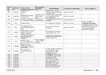
Display
error
code
Classification
level
Display message
(occurrence, response)
Display message
(guidance to
error)
Estimated cause
Trigger of message display
Service response
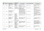
20004
Information
Executing scope color
auto adjustment.
Please wait for a while.
“Execute Auto Adjust” was
selected on the scope color auto
adjustment screen.
Same as on the left
If the message does not
disappear after a while, restart
the processor, and do it again.
In case of repetitive failures,
replace the scope and the patient
PCB.
20007
Warning
Scope color auto
adjustment ends
abnormally.
(1) The scope color auto
adjustment could not be set
within the allowable range.
(2) The provided jig (an
integrating sphere) was not used.
At the time of making scope color
auto adjustment
In case of repetitive failures in
spite of having made the
adjustment again, replace the
scope. In case of more
repetitive failures, replace the
patient PCB.
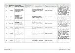
20008
Information
Scope colors are reset to
factory defaults.
When writing data to
EEPROM, perform
"Execute Writing".
“Reset to factory defaults” was
selected on the scope color auto
/ manual adjustment screen, and
scope colors were reset normally
to factory defaults.
Same as on the left
“Execute Writing” is additionally
required in order to write data in
EEPROM.
20009
Error
Unplug and plug back
endoscope, reset the
processor. If the problem
persists, contact your
local FUJIFILM dealer.
Cause: The
processor is in
abnormal state.
“Reset to factory defaults” was
selected on the scope color auto
/ manual adjustment screen, and
scope color resetting to factory
defaults failed.
Same as on the left
In case of repetitive failures,
replace the main PCB and the
patient PCB.
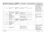
20011
Information
Writing scope color
settings is completed.
“Execute Writing” was selected
on the scope color auto/manual
adjustment screen, and the
writing-in operation ended
normally.
Same as on the left
20012
Error
Unplug and plug back
endoscope, reset the
processor. If the problem
persists, contact your
local FUJIFILM dealer.
Cause: The
processor is in
abnormal state.
“Execute Writing” was selected
on the scope color auto/manual
adjustment screen, and the
writing-in operation failed.
Same as on the left
In case of repetitive failures,
replace the main PCB and the
patient PCB.
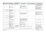
20013
Warning
To end examination,
press the scope button for
more than 1 second.
During examination, pressed the
examination button, and released
it in less than 1 second.
Same as on the left
In case of display with the button
being pressed for more than 1
second, replace the front panel
and the main PCB.
20014
Information
Initializing optical zoom.
Please wait for a while.
After start of examination, or after
having changed the optical zoom
speed, when the optical zoom
button was pressed for the first
time
Same as on the left
If the message does not
disappear after a while, replace
the scope.
Содержание EP-6000
Страница 1: ...Processor EP 6000 FV693A Service Manual SR1807 N002 Ver 1 Oct 2018 ...
Страница 5: ...SS1807 N002 General Table of Contents 1 1 General Table of Contents ...
Страница 13: ...SS1807 N002 Caution in Safety 1 12 Caution in Safety ...
Страница 18: ...SS1807 N002 Caution in Safety 6 12 2 Label 2 1 EP 6000 Labeling Layout FV693A 2 1 1 Labeling chart D B A C ...
Страница 25: ...SS1807 N002 Product Specifications 1 11 Product Specifications ...
Страница 36: ...SS1807 N002 Instruction of System 1 106 Instruction of System ...
Страница 52: ...SS1807 N002 Instruction of System 17 106 In the case of Normal mode In the case of BLI BLI bright or LCI ...
Страница 131: ...SS1807 N002 Instruction of System 96 106 9 EP 6000 Description of Configuration 9 1 Block Diagram ...
Страница 133: ...SS1807 N002 Instruction of System 98 106 ELC PCB Patient PCB APC PCB APC PCB APC PCB DC Pump ...
Страница 139: ...SS1807 N002 Instruction of System 104 106 9 4 Outline of PCB roles ...
Страница 142: ...SS1807 N002 Failure Analysis 1 64 Failure Analysis ...
Страница 206: ...SS1807 N002 Checkup Replacement and Adjustment 1 137 Checkup Replacement and Adjustment ...
Страница 343: ...SS1807 N002 Service Parts List 1 19 Service Parts List ...
Страница 348: ...SS1807 N002 Service Parts List 6 19 6 13 13 16 18 17 17 6 18 14 15 6 9 10 6 12 7 6 11 8 6 5 1 4 3 2 ...
Страница 350: ...SS1807 N002 Service Parts List 8 19 13 12 14 11 14 17 7 7 2 6 15 7 2 3 4 1 5 2 10 9 17 7 7 8 18 12 13 16 ...
Страница 352: ...SS1807 N002 Service Parts List 10 19 2 2 2 4 1 3 3 2 3 3 6 5 ...
Страница 356: ...SS1807 N002 Service Parts List 14 19 1 3 3 4 1 2 1 3 X 4 1 3 3 4 3 3 ...
Страница 358: ...SS1807 N002 Service Parts List 16 19 3 1 2 1 ...
Страница 360: ...SS1807 N002 Service Parts List 18 19 Fig 09 5 4 2 3 1 ...
Страница 362: ...SS1807 N002 Periodical Maintenance 1 15 Periodical Maintenance ...
Страница 377: ...SS1807 N002 Installation 1 68 Installation ...
Страница 381: ...SS1807 N002 Installation 5 68 1 2 Installation onto the Cart Standard System Installation Example ...
Страница 445: ...SS1807 N002 ...

