SS1807-N002
Checkup, Replacement and Adjustment
-
111/137
No.
Inspection items
Inspection specification
How to inspect
Remarks
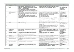
2
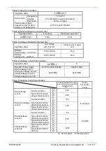
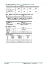
Dielectric Strength
Test
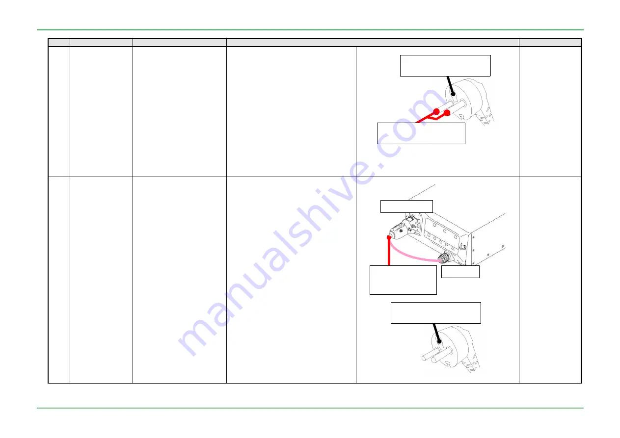
1) Between power
supply - unit
Must not have a discharge or
an electrical breakdown
when the voltage of the
dielectric strength test in
[Table 3] is applied for 1
second.
The sensitive current is 5 mA
or less.
1) Connect the red clips of the dielectric
strength tester with the both Pins on
the power plug.
2) Connect the black clip of the dielectric
strength tester with the GND terminal
on the power plug.
3) Turn on the power of the device to be
measured.
4) Activate the dielectric strength tester
and slowly bring up to the voltage in
[Table 3] of the dielectric strength test.
5) Maintain the voltage of the dielectric
strength test for 1 second and confirm
that there is no electrical breakdown
etc.
6) Return the dielectric strength tester
knob to 0 and remove each clip.
JIG/Equipment
・
Withstand
voltage tester
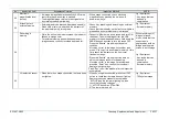
2
2) Between
applied part -
the unit
Must not have a discharge or
an electrical breakdown
when the voltage of the
dielectric strength test in
[Table 3] is applied for 1
second.
1) Connect the “842Y130002*” jig and
“J57721” jig to the processor
2) Connect the red clip on dielectric
strength tester to the “842Y130002*”
jig and the “J57722” jig.
3) Connect the black clip on dielectric
strength tester to the GND terminal of
the power plug.
4) Turn ON the power to the device to be
measured.
5) Activate the dielectric strength tester
and slowly bring up to the voltage in
[Table 3] of the dielectric strength test.
6) Maintain the voltage of the dielectric
strength test for 1 second and confirm
that there is no electrical breakdown
etc.
7) Return the dielectric strength tester
knob to 0 and remove each clip.
JIG/Equipment
・
Withstand
voltage tester
・
842Y130002*
・
J57721
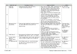
J57721
Connect the red clip
of the dielectric
strength tester
842Y130002*
Connect the black clip of the
dielectric strength tester
Connect the red clips of the
dielectric strength tester.
Connect the black clip of the
dielectric strength tester.
Содержание EP-6000
Страница 1: ...Processor EP 6000 FV693A Service Manual SR1807 N002 Ver 1 Oct 2018 ...
Страница 5: ...SS1807 N002 General Table of Contents 1 1 General Table of Contents ...
Страница 13: ...SS1807 N002 Caution in Safety 1 12 Caution in Safety ...
Страница 18: ...SS1807 N002 Caution in Safety 6 12 2 Label 2 1 EP 6000 Labeling Layout FV693A 2 1 1 Labeling chart D B A C ...
Страница 25: ...SS1807 N002 Product Specifications 1 11 Product Specifications ...
Страница 36: ...SS1807 N002 Instruction of System 1 106 Instruction of System ...
Страница 52: ...SS1807 N002 Instruction of System 17 106 In the case of Normal mode In the case of BLI BLI bright or LCI ...
Страница 131: ...SS1807 N002 Instruction of System 96 106 9 EP 6000 Description of Configuration 9 1 Block Diagram ...
Страница 133: ...SS1807 N002 Instruction of System 98 106 ELC PCB Patient PCB APC PCB APC PCB APC PCB DC Pump ...
Страница 139: ...SS1807 N002 Instruction of System 104 106 9 4 Outline of PCB roles ...
Страница 142: ...SS1807 N002 Failure Analysis 1 64 Failure Analysis ...
Страница 206: ...SS1807 N002 Checkup Replacement and Adjustment 1 137 Checkup Replacement and Adjustment ...
Страница 343: ...SS1807 N002 Service Parts List 1 19 Service Parts List ...
Страница 348: ...SS1807 N002 Service Parts List 6 19 6 13 13 16 18 17 17 6 18 14 15 6 9 10 6 12 7 6 11 8 6 5 1 4 3 2 ...
Страница 350: ...SS1807 N002 Service Parts List 8 19 13 12 14 11 14 17 7 7 2 6 15 7 2 3 4 1 5 2 10 9 17 7 7 8 18 12 13 16 ...
Страница 352: ...SS1807 N002 Service Parts List 10 19 2 2 2 4 1 3 3 2 3 3 6 5 ...
Страница 356: ...SS1807 N002 Service Parts List 14 19 1 3 3 4 1 2 1 3 X 4 1 3 3 4 3 3 ...
Страница 358: ...SS1807 N002 Service Parts List 16 19 3 1 2 1 ...
Страница 360: ...SS1807 N002 Service Parts List 18 19 Fig 09 5 4 2 3 1 ...
Страница 362: ...SS1807 N002 Periodical Maintenance 1 15 Periodical Maintenance ...
Страница 377: ...SS1807 N002 Installation 1 68 Installation ...
Страница 381: ...SS1807 N002 Installation 5 68 1 2 Installation onto the Cart Standard System Installation Example ...
Страница 445: ...SS1807 N002 ...


