SS1807-N002
Product Specifications
-
2/11
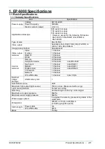
1. EP-6000 Specifications
1.1 Basic Specifications
1.1.1 Catalog Specifications
Item
Specification
Power supply
Voltage
AC100-240V
Power frequency
50/60Hz
Electric current (rated)
2.0-1.1A
Applicable endoscope
600 system scopes
700 system scopes
500 system scopes
However, except for the following 590 series
EG-530UT 2, EG-530UT, EG-530UR 2,
EG-530UR
Type of color
PAL / NTSC
Video output
Selectable from 1920×1080_60p (Full HD) or
1280 x 1024_60p (SXGA)
Image pickup method
Simultaneous
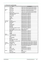
Video output
terminal
Video
1 Channel
S video
1 Channel
RGB TV
1 Channel
DVI-D
2 Channels
Control
terminal
Remote
2 Channels
Peripheral device
2 Channels
note:RS-232C
Key board
1 Channel
note:USB1.1
Reader
1 Channel
note:USB1.1
Digital printer
1 Channel
note:USB2.0
Foot switch
1 Channel
Network
1 Channel
WC-LINK cable
1 Channel
note: 37pin
External
image
storage
USB memory slot
1
Illumination source
LED
Maximum light output (light source)
750lm or less
(Measured with our jig
)
Light cooling method
Forced air cooling
Demining
Automatic light control by control signal
Maximum air supply pressure
65kPa
Maximum water supply pressure
65kPa
Water supply system
It supplies the water by pressurizing inside of the
water tank.
Dimensions
395(W) x 210(H) x 485(D)mm
(including projective parts)
Cable length
Power cable
3m
WC-LINK cable
26cm
Mass
15.0kg
Содержание EP-6000
Страница 1: ...Processor EP 6000 FV693A Service Manual SR1807 N002 Ver 1 Oct 2018 ...
Страница 5: ...SS1807 N002 General Table of Contents 1 1 General Table of Contents ...
Страница 13: ...SS1807 N002 Caution in Safety 1 12 Caution in Safety ...
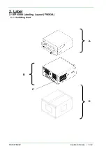
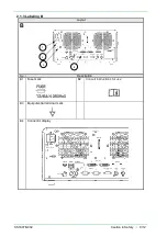
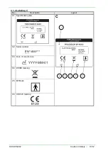
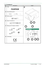
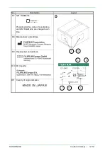
Страница 18: ...SS1807 N002 Caution in Safety 6 12 2 Label 2 1 EP 6000 Labeling Layout FV693A 2 1 1 Labeling chart D B A C ...
Страница 25: ...SS1807 N002 Product Specifications 1 11 Product Specifications ...
Страница 36: ...SS1807 N002 Instruction of System 1 106 Instruction of System ...
Страница 52: ...SS1807 N002 Instruction of System 17 106 In the case of Normal mode In the case of BLI BLI bright or LCI ...
Страница 131: ...SS1807 N002 Instruction of System 96 106 9 EP 6000 Description of Configuration 9 1 Block Diagram ...
Страница 133: ...SS1807 N002 Instruction of System 98 106 ELC PCB Patient PCB APC PCB APC PCB APC PCB DC Pump ...
Страница 139: ...SS1807 N002 Instruction of System 104 106 9 4 Outline of PCB roles ...
Страница 142: ...SS1807 N002 Failure Analysis 1 64 Failure Analysis ...
Страница 206: ...SS1807 N002 Checkup Replacement and Adjustment 1 137 Checkup Replacement and Adjustment ...
Страница 343: ...SS1807 N002 Service Parts List 1 19 Service Parts List ...
Страница 348: ...SS1807 N002 Service Parts List 6 19 6 13 13 16 18 17 17 6 18 14 15 6 9 10 6 12 7 6 11 8 6 5 1 4 3 2 ...
Страница 350: ...SS1807 N002 Service Parts List 8 19 13 12 14 11 14 17 7 7 2 6 15 7 2 3 4 1 5 2 10 9 17 7 7 8 18 12 13 16 ...
Страница 352: ...SS1807 N002 Service Parts List 10 19 2 2 2 4 1 3 3 2 3 3 6 5 ...
Страница 356: ...SS1807 N002 Service Parts List 14 19 1 3 3 4 1 2 1 3 X 4 1 3 3 4 3 3 ...
Страница 358: ...SS1807 N002 Service Parts List 16 19 3 1 2 1 ...
Страница 360: ...SS1807 N002 Service Parts List 18 19 Fig 09 5 4 2 3 1 ...
Страница 362: ...SS1807 N002 Periodical Maintenance 1 15 Periodical Maintenance ...
Страница 377: ...SS1807 N002 Installation 1 68 Installation ...
Страница 381: ...SS1807 N002 Installation 5 68 1 2 Installation onto the Cart Standard System Installation Example ...
Страница 445: ...SS1807 N002 ...


