SS1807-N002
Installation
-
22/68
1.13 Power Source
Installation of this system must be performed according to EN 60601-1.
When installing this system, follow the descriptions below.
<Power connection for using equipment in combination>
The equipment which can be used in combination with this system is divided into the following three
types according to its power connection.
(1) Equipment which is directly combined with this system (Applicable to EN 60601-1)
The equipment that makes up this product and system.
Examples of such equipment are shown in Table 1.1.
(2) Equipment which can be used when its power is supplied from a power source other than the
cart in which this system is installed. (Applicable to EN 60601-1)
Examples of such equipment are shown in Table 1.2.
(3) Peripherals which are used when required power is supplied from an insulated transformer
applicable to EN 60601-1 (Applicable or conforming to EN 60601-1 or EN60950)
Examples of such equipment are shown in Table 1.3.
The equipment other than these three types may not be safe. Do not use such equipment.
In combination with any of the equipment above, all configurations shall comply with the requirement
for ME systems of EN 60601-1.
In any combination of the equipment above, all configurations must comply with the requirements of
ME systems of EN60601-1.
◆
Note
◆
・
These combinations are determined based on electrical safety. The performance of the equipment
depends on the specifications of each manufacturer.
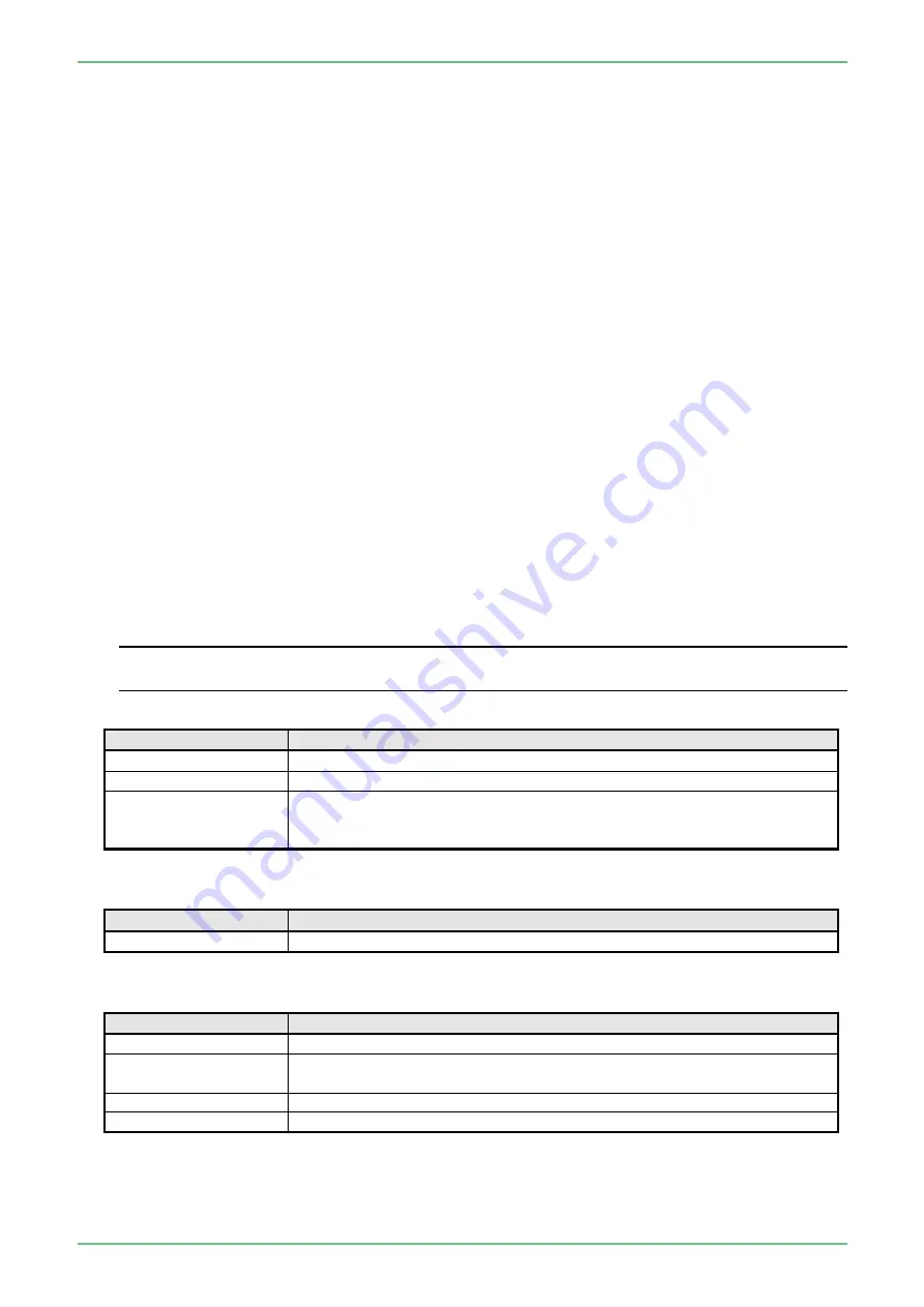
Table 1.1 Equipment configuring the system
Type
Model
Processor
EP-6000
Data Keyboard
DK-6000U or DK-6000E
*1
Endoscope
700 system scopes
600 system scopes
500 system scopes
*1
:
The type of the data keyboard varies depending on the country.
Table 1.2 Medical equipment used when its power is supplied from other power source
Type
Model
Electrosurgical Unit
*2
-
*2
:
For electrosurgical units that can be combined, see the instruction manual of the endoscope.
Table 1.3 Peripherals used when its power is supplied from an insulated transformer
Type
Model
Ultrasonic Processor
SU-1,SP-900
LCD Monitor
CL-22(FUJIFILM), CL-24(FUJIFILM), CCL220/AR(JVC KENWOOD)
CCL244/AR(JVC KENWOOD)
Printer
UP-25MD(SONY), UP-55MD(SONY), UP-D25MD(SONY)
Video Recorder
HVO-3300MT(SONY), HVO-1000MD(SONY), HVO-550MD(SONY)
Содержание EP-6000
Страница 1: ...Processor EP 6000 FV693A Service Manual SR1807 N002 Ver 1 Oct 2018 ...
Страница 5: ...SS1807 N002 General Table of Contents 1 1 General Table of Contents ...
Страница 13: ...SS1807 N002 Caution in Safety 1 12 Caution in Safety ...
Страница 18: ...SS1807 N002 Caution in Safety 6 12 2 Label 2 1 EP 6000 Labeling Layout FV693A 2 1 1 Labeling chart D B A C ...
Страница 25: ...SS1807 N002 Product Specifications 1 11 Product Specifications ...
Страница 36: ...SS1807 N002 Instruction of System 1 106 Instruction of System ...
Страница 52: ...SS1807 N002 Instruction of System 17 106 In the case of Normal mode In the case of BLI BLI bright or LCI ...
Страница 131: ...SS1807 N002 Instruction of System 96 106 9 EP 6000 Description of Configuration 9 1 Block Diagram ...
Страница 133: ...SS1807 N002 Instruction of System 98 106 ELC PCB Patient PCB APC PCB APC PCB APC PCB DC Pump ...
Страница 139: ...SS1807 N002 Instruction of System 104 106 9 4 Outline of PCB roles ...
Страница 142: ...SS1807 N002 Failure Analysis 1 64 Failure Analysis ...
Страница 206: ...SS1807 N002 Checkup Replacement and Adjustment 1 137 Checkup Replacement and Adjustment ...
Страница 343: ...SS1807 N002 Service Parts List 1 19 Service Parts List ...
Страница 348: ...SS1807 N002 Service Parts List 6 19 6 13 13 16 18 17 17 6 18 14 15 6 9 10 6 12 7 6 11 8 6 5 1 4 3 2 ...
Страница 350: ...SS1807 N002 Service Parts List 8 19 13 12 14 11 14 17 7 7 2 6 15 7 2 3 4 1 5 2 10 9 17 7 7 8 18 12 13 16 ...
Страница 352: ...SS1807 N002 Service Parts List 10 19 2 2 2 4 1 3 3 2 3 3 6 5 ...
Страница 356: ...SS1807 N002 Service Parts List 14 19 1 3 3 4 1 2 1 3 X 4 1 3 3 4 3 3 ...
Страница 358: ...SS1807 N002 Service Parts List 16 19 3 1 2 1 ...
Страница 360: ...SS1807 N002 Service Parts List 18 19 Fig 09 5 4 2 3 1 ...
Страница 362: ...SS1807 N002 Periodical Maintenance 1 15 Periodical Maintenance ...
Страница 377: ...SS1807 N002 Installation 1 68 Installation ...
Страница 381: ...SS1807 N002 Installation 5 68 1 2 Installation onto the Cart Standard System Installation Example ...
Страница 445: ...SS1807 N002 ...

