SS1807-N002
Checkup, Replacement and Adjustment
-
122/137
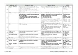
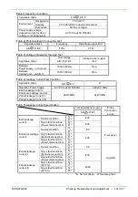
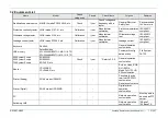
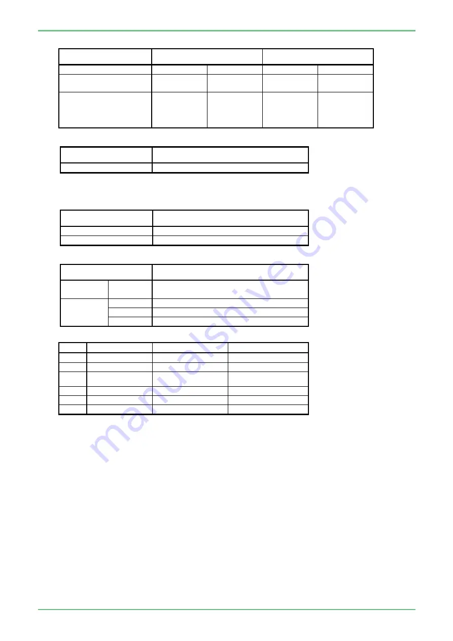
[Table 6] Power Supply (For the power supply cord with specification as 230V)
Applicable Class
A,B,
○
C ,E,F
D
Power input
264V/60Hz
90V/50Hz
198V/50Hz
242V/50Hz
Specification Center for
Power Input
0.54A
1.12A
0.60A
0.60A
Must be 10% of
the Specification
Maximum for Power
Input
0.59A
1.23A
0.66A
0.66A
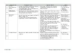
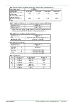
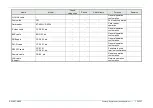
[Table7] Inspection criterion for the force to pull out a one-connector scope.
Applicable Class
A,B,
○
C ,D,E,F
Force to pull out
-22N ~ -43N
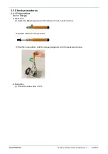
• Inspect the force based on the average value of five measurements.
• A minus sign shows that the force is in the pulling direction.
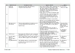
[Table 8] Maximum Light Quantity Specification
Applicable Class
A,B,
○
C ,D,E,F
Mode
Maximum light emission of light source
Normal light mode
1241mW ~ 1612mW
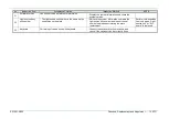
[Table 9] Pump Specification
Applicable Class
A,B,
○
C ,D,E,F
Air supply
pressure
H
50±10kPa
Air supply
volume
H
1.8±0.3 l/min at 35kPa
M
1.4±0.3 l/min at 35kPa
L
1.1±0.3 l/min at 35kPa
[Table 10] Category
Sign
Product Code
Serial Number
Destination
A
FV691A
*V691G***
Japan
B
FV692A
*V692G***
USA
○
C
FV693A
*V693K***
EU
D
FV693A-8
*V693G***
China
E
FV694A
*V694G***
LA
F
FV696A
*V696K***
AP
Содержание EP-6000
Страница 1: ...Processor EP 6000 FV693A Service Manual SR1807 N002 Ver 1 Oct 2018 ...
Страница 5: ...SS1807 N002 General Table of Contents 1 1 General Table of Contents ...
Страница 13: ...SS1807 N002 Caution in Safety 1 12 Caution in Safety ...
Страница 18: ...SS1807 N002 Caution in Safety 6 12 2 Label 2 1 EP 6000 Labeling Layout FV693A 2 1 1 Labeling chart D B A C ...
Страница 25: ...SS1807 N002 Product Specifications 1 11 Product Specifications ...
Страница 36: ...SS1807 N002 Instruction of System 1 106 Instruction of System ...
Страница 52: ...SS1807 N002 Instruction of System 17 106 In the case of Normal mode In the case of BLI BLI bright or LCI ...
Страница 131: ...SS1807 N002 Instruction of System 96 106 9 EP 6000 Description of Configuration 9 1 Block Diagram ...
Страница 133: ...SS1807 N002 Instruction of System 98 106 ELC PCB Patient PCB APC PCB APC PCB APC PCB DC Pump ...
Страница 139: ...SS1807 N002 Instruction of System 104 106 9 4 Outline of PCB roles ...
Страница 142: ...SS1807 N002 Failure Analysis 1 64 Failure Analysis ...
Страница 206: ...SS1807 N002 Checkup Replacement and Adjustment 1 137 Checkup Replacement and Adjustment ...
Страница 343: ...SS1807 N002 Service Parts List 1 19 Service Parts List ...
Страница 348: ...SS1807 N002 Service Parts List 6 19 6 13 13 16 18 17 17 6 18 14 15 6 9 10 6 12 7 6 11 8 6 5 1 4 3 2 ...
Страница 350: ...SS1807 N002 Service Parts List 8 19 13 12 14 11 14 17 7 7 2 6 15 7 2 3 4 1 5 2 10 9 17 7 7 8 18 12 13 16 ...
Страница 352: ...SS1807 N002 Service Parts List 10 19 2 2 2 4 1 3 3 2 3 3 6 5 ...
Страница 356: ...SS1807 N002 Service Parts List 14 19 1 3 3 4 1 2 1 3 X 4 1 3 3 4 3 3 ...
Страница 358: ...SS1807 N002 Service Parts List 16 19 3 1 2 1 ...
Страница 360: ...SS1807 N002 Service Parts List 18 19 Fig 09 5 4 2 3 1 ...
Страница 362: ...SS1807 N002 Periodical Maintenance 1 15 Periodical Maintenance ...
Страница 377: ...SS1807 N002 Installation 1 68 Installation ...
Страница 381: ...SS1807 N002 Installation 5 68 1 2 Installation onto the Cart Standard System Installation Example ...
Страница 445: ...SS1807 N002 ...


