Operating Instructions
Modular Safety Control System MSC
84
(Translation of the original operating instructions) 2121331-04-04/19
If the OUTPUT is at logic level "high" (TRUE), the FBK signal must be at the logic level "low" (FALSE) within the time set and
vice versa.
Otherwise the OUTPUT output changes to the low level (FALSE) and the error is signaled on the base unit MSC-CB by the
flashing of the CLEAR LED for the OSSD in the error mode.
Enable Error Out: If selected, the ERROR_OUT output is enabled.
If an error is detected on the external FBK signal,
the output changes to the logic level "high" (TRUE).
The
Error OUT
signal is reset if one of the following events occurs:
1. The system is switched off and on again.
2. The RESET MSC-CB operator is activated.
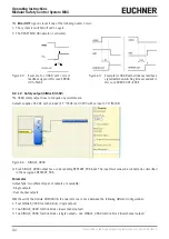
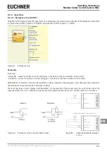
Figure 69: Example for OSSD with correct
feedback signal: in this case
ERROR OUT=FALSE
Figure 70: Example for OSSD with erroneous feedback signal
(external switching time exceeded): in this case ERROR
OUT=TRUE
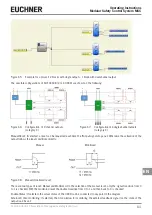
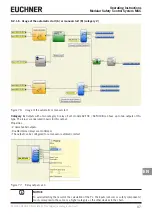
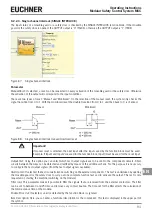
9.2.1.3. Signal output (STATUS)
Using the STATUS output, every point in the diagram can be monitored by connecting it to the In input. The output supplies
24 VDC with an input of "1" (TRUE) and 0 VDC with an input of "0" (FALSE).
Figure 71: Status
Important!
The STATUS output is
NOT
a safety output.
Содержание MSC
Страница 1: ...EN Operating Instructions Installation and use Modular Safety Control System MSC ...
Страница 171: ......
Страница 173: ......

