Operating Instructions
Modular Safety Control System MSC
144
(Translation of the original operating instructions) 2121331-04-04/19
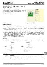
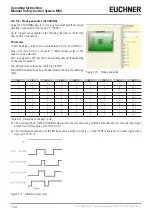
9.4.5.6. Clock generation (CLOCKING)
Using the CLOCKING operator a clock signal output with the required
duration is generated if the input is "1" (TRUE).
Up to 7 inputs are available on the Clocking operator to control the
duty cycle on the output.
Parameter
Time: The delay can be set to a value between 10 ms and 1098.3 s.
Duty cycle choice: Up to 7 inputs for 7 different duty cycles on the
output can be selected.
The clock signal on OUT has the corresponding duty cycle depending
on the input activated.
The EN input must always be set to high (TRUE).
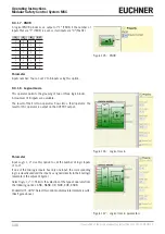
You will find information on how the operator functions in the following
table.
Figure 176: Clock generation
EN
10 %
20 %
30 %
40 %
60 %
70 %
80 %
OUT
0
0
0
0
0
0
0
0
0
1
0
0
0
0
0
0
0
50 %
1
1
0
0
0
0
0
0
10 %
1
0
1
0
0
0
0
0
20 %
1
0
0
1
0
0
0
0
30 %
1
0
0
0
1
0
0
0
40 %
1
0
0
0
0
1
0
0
60 %
1
0
0
0
0
0
1
0
70 %
1
0
0
0
0
0
0
1
80 %
1
1
0
0
0
0
0
1
90 %
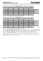
Table 69: Selection of the duty cycle
¨
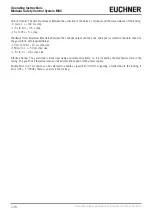
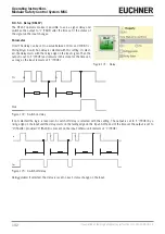
The circuit upstream of the CLOCKING operator must ensure that, along with the EN enable, there is only one input signal
present (apart from duty cycle 10 %, 80 %).
¨
The simultaneous presence of the EN input and a number of inputs > 1 high (TRUE) generates an output signal with a
duty cycle of 50 %.
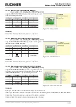
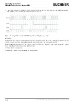
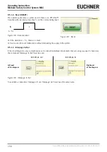
Figure 177: Different duty cycles
Содержание MSC
Страница 1: ...EN Operating Instructions Installation and use Modular Safety Control System MSC ...
Страница 171: ......
Страница 173: ......

