81
2121331-04-04/19 (Translation of the original operating instructions)
Operating Instructions
Modular Safety Control System MSC
EN
9.2. Item-specific function blocks
9.2.1. Output items
9.2.1.1. Safety outputs (OSSD)
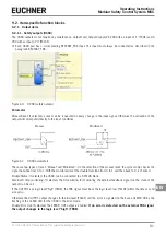
The OSSD outputs do not require any maintenance. Output1 and Output2 supply 24 VDC with an input of "1" (TRUE) and 0
VDC with an input of "0" (FALSE).
¨
Each OSSD pair has a corresponding RESTART_FBK input. This input must always be connected as described in the
paragraph RESTART_FBK.
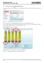
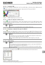
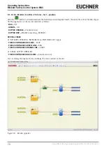
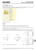
Figure 60: OSSD (safety outputs)
Parameter
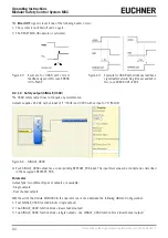
Manual Reset: If selected, a reset can be requested on every change in the input signal. Otherwise the activation of the
output will correspond directly to the input conditions.
Manual
Monitored
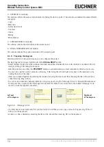
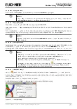
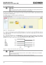
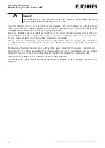
Figure 61: OSSD parameters
There are two types of reset: "Manual" and "Monitored". On the selection of the manual reset, the system only checks the
signal transition from 0 to 1. With the monitored reset the double transition from 0 to 1 and then back to 0 is checked.
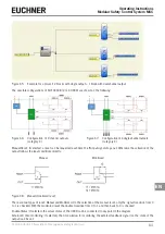
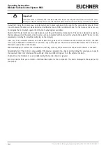
Enable Status: If selected, the OSSD can be connected to a STATUS block.
External K time monitoring: If selected, the time window for monitoring the external feedback signal (on the state of the
output) can be set.
If the OUTPUT is at logic level "high" (TRUE), the FBK signal must be at the logic level "low" (FALSE) within the time set and
vice versa.
Otherwise the OUTPUT output changes to the low level (FALSE) and the error is signaled on the base unit MSC-CB by the
flashing of the CLEAR LED for the OSSD in the error mode.
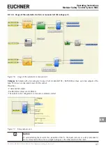
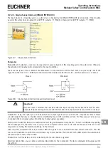
Enable Error Out: If selected, the ERROR_OUT output is enabled.
If an error is detected on the external FBK signal,
the output changes to the logic level "high" (TRUE).
Содержание MSC
Страница 1: ...EN Operating Instructions Installation and use Modular Safety Control System MSC ...
Страница 171: ......
Страница 173: ......


