Operating Instructions
Modular Safety Control System MSC
126
(Translation of the original operating instructions) 2121331-04-04/19
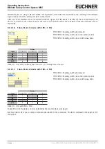
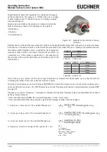
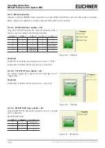
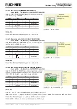
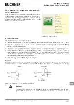
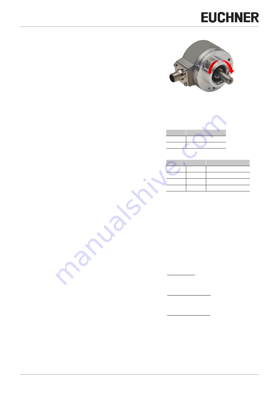
Enable Direction: Select this parameter to activate the DIR output
on the function block. This output is "1" (TRUE) if the axis is rotating
counter clockwise and "0" (FALSE) if the axis is rotating clockwise
(see adjacent figure).
Direction decision: Defines the direction of rotation for which the
limits entered are activated. The following can be selected:
Ì
Bidirectional
Ì
Clockwise
Ì
Counterclockwise
Figure 137: Example for the rotation of the axis
clockwise
If "Bidirectional" is selected, the measurement is made on exceeding the limit entered, both clockwise and counter clockwise.
If "Clockwise" or "Counterclockwise" is selected, the measurement is only made if the axis is rotating in the selected direction.
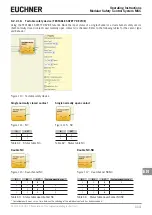
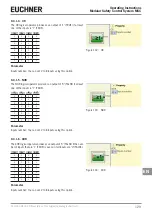
Thresholds number: Number of max. speed limits. By changing this
value the number of limits is increased or reduced from at least 1 to
a maximum of 4. If the number is greater than 1, the input pins for
the selection of the specific limit appear in the bottom part of the
function block.
In1
Limits
0
Speed 1
1
Speed 2
Table 67: 2 limits set
In2
In1
Limits
0
0
Speed 1
0
1
Speed 2
1
0
Speed 3
1
1
Speed 4
Table 68: 4 limits set
Pitch: If the axis type "Linear" and the sensor type "Rotational" are selected, this field enables you to enter the pitch for
converting the rotation of the sensor into the distance covered.
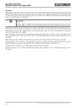
Proximity choice: Enables you to select between PNP, NPN, NO contact, NC contact, 3-wire or 4-wire for the proximity sensor.
To ensure Performance Level = Pl e, PNP NO must be used (see “Proximity switch input on speed monitoring modules SPM”
on page 29).
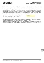
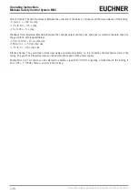
Frequency zero speed / Frequency 1 / Frequency 2: Indicates the maximum frequency values calculated fM and fm (reduced
by the hysteresis entered).
Ì
If the value indicated is GREEN, the calculated frequency is in the correct range.
Ì
If the value indicated is RED, the parameters given in the following formulas must be changed.
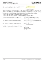
1. Rotary axis, rotary sensor. The calculated frequency is:
f Hz
[ ]
=
rpm rev /min
[
]
60
*
Resolution pulses/rev
[
]
2. Linear axis, rotary sensor. The calculated frequency is:
f Hz
[ ]
=
speed m/min
[
]
*
1000
60
*
pitch mm/rev
[
]
*
Resolution pulses/rev
[
]
3. Linear axis, linear sensor. The calculated frequency is:
f Hz
[ ]
=
speed mm/s
[
]
*
1000
Resolution µm/pulse
[
]
4. Hysteresis. Only to be changed if: fM = green; fm = red
KEY:
f = Frequency
rpm = Rotary speed
Resolution = Measurement
speed = Linear speed
pitch = Pitch
Содержание MSC
Страница 1: ...EN Operating Instructions Installation and use Modular Safety Control System MSC ...
Страница 171: ......
Страница 173: ......

