Operating Instructions
Modular Safety Control System MSC
168
(Translation of the original operating instructions) 2121331-04-04/19
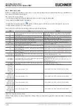
9.6.3. MSC error codes
If there is a malfunction, the MSC system sends a code, corresponding to the error detected by the base unit MSC-CB, to
the software EUCHNER Safety Designer.
The code can be read as follows:
Ì
Connect base unit MSC-CB (indicates ERROR via LED on) to the PC using the USB cable.
Ì
Start software EUCHNER SAFETY DESIGNER.
Ì
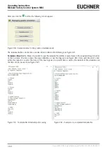
Establish the connection using the
button; a window appears with the password prompt; type the password; a
window appears with the error code acquired.
All possible errors with the corresponding solution are listed in the following.
CODE
FAIL
SOLUTION
19D
The two microcontrollers MSC-CB do not have the same hardware/soft-
ware configuration.
CHECK MSC-CB AND MSC PLUG CONNECTORS ON THE EXTENSION
MODULES FOR CORRECT SEATING. REPLACE PLUG CONNECTORS
IF NECESSARY.
66D
There are two or more extension modules with the same node number.
CHECK CONNECTIONS – PIN 2 and 3 ON THE EXTENSION MODULES
68D
Maximum number of extension modules exceeded.
DISCONNECT EXCESS MODULES (MAX: 14)
70D
A change in the node number has been detected on one or more modules. CHECK CONNECTIONS – PIN 2 and 3 ON THE EXTENSION MODULES
73D
An external error has been detected on a slave module.
SEE ERROR CODE ON THE MODULE FOR MORE INFORMATION
96D ÷ 101D
Error in relation to the M-A1 memory card.
REPLACE M-A1 MEMORY CARD
137D
From a module AZ-FO4 or AZ-FO4O8 – EDM error on the pair RELAY1 and
RELAY2 for category 4.
CHECK CONNECTION OF THE EXTERNAL FEEDBACK CONTACTORS
147D
From a module AZ-FO4 or AZ-FO4O8 – EDM error on the pair RELAY2 and
RELAY3 for category 4.
CHECK CONNECTION OF THE EXTERNAL FEEDBACK CONTACTORS
157D
From a module AZ-FO4 or AZ-FO4O8 – EDM error on the pair RELAY3 and
RELAY4 for category 4.
CHECK CONNECTION OF THE EXTERNAL FEEDBACK CONTACTORS
133D (Proxi1)
140D (Proxi2)
From a module SPM2, SPM1 or SPM0 – overfrequency acquired on the
proximity switch input.
THE INPUT FREQUENCY MUST BE < 5 KHz
136D (Encoder1)
143D (Encoder2)
From a module SPM2, SPM1 or SPM0 – encoder input signals outside the
standard (duty cycle, phase offset) acquired.
THE DUTY CYCLE MUST HAVE THE FOLLOWING VALUE: 50 % + 33 %
OF THE PERIOD (HTL, TTL).
THE PHASE OFFSET MUST HAVE THE FOLLOWING VALUE: 90° + 45°
(HTL, TTL)
(not applicable to SIN/COS)
138D (Encoder1)
145D (Encoder2)
From a module SPM2, SPM1 or SPM0 – overfrequency acquired on the
encoder input.
THE INPUT FREQUENCY MUST BE:
< 500 kHz (TTL, SIN/COS); < 300 kHz (HTL).
130D 135D
137D 138D
140D 194D
197D 198D
199D 201D
202D 203D
205D
Error on the static output OSSD1.
CHECK CONNECTIONS FOR OSSD1 ON MODULE WITH ERROR
144D 149D
151D 152D
154D 208D 211D
212D 213D 215D
216D 217D 219D
Error on the static output OSSD2.
CHECK CONNECTIONS FOR OSSD2 ON MODULE WITH ERROR
158D 163D
165D 166D
168D 222D 225D
226D 227D 229D
230D 232D 233D
Error on the static output OSSD3.
CHECK CONNECTIONS FOR OSSD3 ON MODULE WITH ERROR
172D 177D
179D 180D
182D 236D
239D 240D 241D
243D 244D 245D
247D
Error on the static output OSSD4.
CHECK CONNECTIONS FOR OSSD4 ON MODULE WITH ERROR
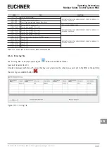
Table 78: Overview of error codes
All other codes relate to an internal malfunction. Please check any malfunctions against this table and state on returning to
EUCHNER.
Содержание MSC
Страница 1: ...EN Operating Instructions Installation and use Modular Safety Control System MSC ...
Страница 171: ......
Страница 173: ......

