Operating Instructions
Modular Safety Control System MSC
102
(Translation of the original operating instructions) 2121331-04-04/19
9.2.2.9. Light barrier (PHOTOCELL)
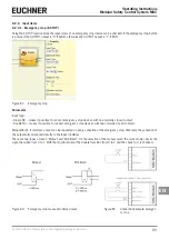
Using the PHOTOCELL function block the input status of an optoelectronic safety light barrier is checked.
If the beam from the light barrier is obscured (output on the light barrier FALSE), the OUTPUT output is "0" (FALSE). If, con-
versely, the beam is not obscured (output on the light barrier TRUE), the OUTPUT output is "1" (TRUE).
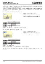
Figure 100: Light barrier
Parameter
Manual Reset: If selected, a reset can be requested on every activation of the safety light barrier. Otherwise the activation
of the output will correspond directly to the input conditions.
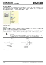
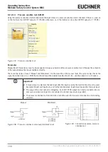
There are two types of reset: "Manual" and "Monitored". On the selection of the manual reset, the system only checks the
signal transition from 0 to 1. With the monitored reset the double transition from 0 to 1 and then back to 0 is checked.
Manual
Monitored
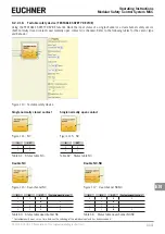
Figure 101: Light barrier manual/monitored reset
Figure 102: Connection example, light barrier
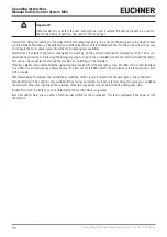
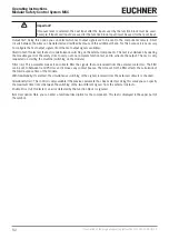
Important!
Ì
A test output is obligatory and can be selected using one of the 4 possible OUT_TEST outputs.
Ì
Attention: If RESET is selected, the next input must be used for the reset. Example: If INPUT1 is
used for the function, INPUT2 must be used for the RESET.
Ì
The reaction time of the light barrier must be > 2 ms and < 20 ms.
Output Test: Using this option you can select which test output signals are to be sent to the test input on the light barrier.
Short circuits between the wires can be detected and rectified by means of this additional check. For this purpose it is
necessary to configure the test output signals (from the test output signals available).
StartUp Test: If selected, the test is undertaken on switching on the external components. This test is undertaken by cover-
ing and clearing the safety light barrier to carry out one complete function test and to activate the output. This test is only
requested on starting the machine (on switching on the module).
Filter (ms): This parameter makes it possible to filter the signals that are received from the external contactors. This filter
can be set to between 3 and 250 ms and removes any contact bounce. The time set for the filter affects the calculation of
the total response time of the module.
Содержание MSC
Страница 1: ...EN Operating Instructions Installation and use Modular Safety Control System MSC ...
Страница 171: ......
Страница 173: ......


