


167
2121331-04-04/19 (Translation of the original operating instructions)
Operating Instructions
Modular Safety Control System MSC
EN
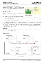
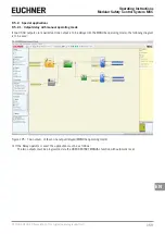
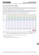
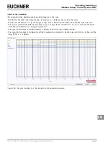
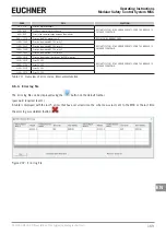
Result of the simulation
The signals from the simulation are shown in the diagram. In this case:
Ì
At 2000 ms the "Safe Zone" signal changes to logic level 1. It indicates the closing of the gate.
Ì
At 3000 ms the "Start_Press" signal changes to logic level 1. It indicates the request for activation by the operator.
Ì
The output signal from the AND operator "Op1" changes to logic level 1 at 3000 ms. This occurs when the two inputs
"Safe Zone" and "Start_Press" change to logic level 1.
Ì
The signal on the output of the AND operator is delayed by 2000 ms by the Delay operator.
Ì
The signal on the output of the delay block "Op2" provides the command to close the relay at 5000 ms. At this point the
relay "M_Press" is activated.
Figure 206: Diagram resulting from the simulation of the application example
Содержание MSC
Страница 1: ...EN Operating Instructions Installation and use Modular Safety Control System MSC ...
Страница 171: ......
Страница 173: ......