Product Description
86
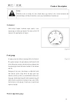
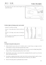
Water temperature gauge indicates engine coolant
temperatures with scales.
Different coolant temperature ranges are indicated using
different colors:
◇
Green area = normal operating temperature
◇
Red area = engine overheating
Do not accelerate cold engine directly to maximum speed.
Wait until it reaches normal operating temperature (the pointer
moves to the green area).
Fig. 3-15
Notice:
Shut down the engine immediately if the pointer moves to the red zone.
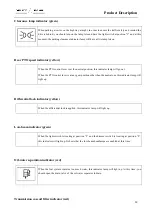
Trailer brake lamp (red)
When the trailer brake system has failed during operation, this indicator lamp will light up.
When the air brake system has its pressure lower than 0.4Mpa, this indicator lamp will light up, it
indicates a fault of the brake gas path and immediate troubleshooting should be needed.
If the air pressure is found insufficient when the key is turned on but the engine has not been started,
it is normal when this indicator lamp is on.
Front-wheel drive indicator (yellow)
When the front-wheel drive is applied, this indicator lamp will light up.
Содержание FL35-70HP Series
Страница 21: ...Product Mark 20 1 Security Considerations ...
Страница 57: ...Product Mark 56 Fig 1 35 Fig 1 36 ...
Страница 58: ...Product Mark 57 Fig 1 37 Fig 1 38 ...
Страница 62: ...Product Mark 61 Rear transverse board safety label To prevent personal injury do not ride or stand here ...
Страница 70: ...69 2 Product Mark ...
Страница 74: ...73 Page Left Intentionally Blank ...
Страница 75: ...Product Description 74 3 Product Description ...
Страница 77: ...Product Description 76 Fig 3 2 3 1 2 Appearance of tractor equipped with cab ...
Страница 81: ...Product Description 80 ...
Страница 84: ...Product Description 83 3 7 Notice Check whether the steering wheel is fixed firmly before driving ...
Страница 113: ...Product Description 112 ...
Страница 124: ...Electrical system 123 4 Operation Instructions ...
Страница 157: ...Electrical system 156 ...
Страница 162: ...Electrical system 161 Fig 4 32 Three point linkage Model 2 ...
Страница 168: ...Electrical system 167 Fig 4 41 Diagram for movement of the hitch mechanism configuration 3 Wheels ...
Страница 189: ...Electrical system 188 5 Wheels ...
Страница 208: ...Electrical system 207 6 Electrical System ...
Страница 230: ...Electrical system 229 requirements 6 6 Electrical Schematic Diagram ...
Страница 235: ...234 7 On board Spare Parts Tools and Quick wear Parts ...
Страница 241: ...240 ...
Страница 242: ...241 8 Maintenance Specification ...
Страница 288: ...287 Fig 8 35 ...
Страница 338: ...Operation Instructions 337 9 Troubleshooting ...
Страница 353: ...352 10 Tractor Storage and Unpack ...
Страница 358: ...Tractor Storage and Unpack 357 11 Delivery Acceptance and Transportation ...
Страница 361: ...360 ...
Страница 362: ...361 12 Disassembly and Disposal ...
Страница 365: ...Warranty Contents 364 13 Warranty Contents ...
Страница 411: ...Appendix 410 15 Appendix ...

