


Electrical system
202
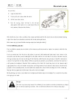
Adjust the wheel tread width as follows:
●
Park your tractor on a flat ground as described in the
operating manual for tractor parking.
●
Use a jack to lift one of the two wheels off the ground
and place a suitable support.
●
Unscrew the bolt
①
, and
④
on the lower sleeve as
well as the hub cover
②
and the hub
③
and then move
the wheel to take down the hub from the sleeve.
●
Slide the hub cap
②
and hub
③
on the drive shaft
⑤
to the specified position, and then fully tighten the
bolts
①
and
④
.
Fig. 5-13
Important:
Do adjust the two wheels in the same way.
5.6.Ballast
5.6.1.Capacity for carrying ballast
Danger:
We recommend that you use appropriate safety equipment as much as possible when carrying the ballast.
5.6.2.
According to the requirements of the statutory regulations, a man can carry the weight no more than 30kg while a
woman no more than 20kg.
The tractor may carry different kinds of ballast:
●
Cast iron "box-shaped" blocks;
●
Use bolts to fix cast iron pieces;
●
Intermediate plate;
Содержание FL35-70HP Series
Страница 21: ...Product Mark 20 1 Security Considerations ...
Страница 57: ...Product Mark 56 Fig 1 35 Fig 1 36 ...
Страница 58: ...Product Mark 57 Fig 1 37 Fig 1 38 ...
Страница 62: ...Product Mark 61 Rear transverse board safety label To prevent personal injury do not ride or stand here ...
Страница 70: ...69 2 Product Mark ...
Страница 74: ...73 Page Left Intentionally Blank ...
Страница 75: ...Product Description 74 3 Product Description ...
Страница 77: ...Product Description 76 Fig 3 2 3 1 2 Appearance of tractor equipped with cab ...
Страница 81: ...Product Description 80 ...
Страница 84: ...Product Description 83 3 7 Notice Check whether the steering wheel is fixed firmly before driving ...
Страница 113: ...Product Description 112 ...
Страница 124: ...Electrical system 123 4 Operation Instructions ...
Страница 157: ...Electrical system 156 ...
Страница 162: ...Electrical system 161 Fig 4 32 Three point linkage Model 2 ...
Страница 168: ...Electrical system 167 Fig 4 41 Diagram for movement of the hitch mechanism configuration 3 Wheels ...
Страница 189: ...Electrical system 188 5 Wheels ...
Страница 208: ...Electrical system 207 6 Electrical System ...
Страница 230: ...Electrical system 229 requirements 6 6 Electrical Schematic Diagram ...
Страница 235: ...234 7 On board Spare Parts Tools and Quick wear Parts ...
Страница 241: ...240 ...
Страница 242: ...241 8 Maintenance Specification ...
Страница 288: ...287 Fig 8 35 ...
Страница 338: ...Operation Instructions 337 9 Troubleshooting ...
Страница 353: ...352 10 Tractor Storage and Unpack ...
Страница 358: ...Tractor Storage and Unpack 357 11 Delivery Acceptance and Transportation ...
Страница 361: ...360 ...
Страница 362: ...361 12 Disassembly and Disposal ...
Страница 365: ...Warranty Contents 364 13 Warranty Contents ...
Страница 411: ...Appendix 410 15 Appendix ...