


Electrical system
186
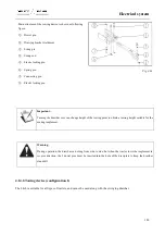
Main structure of the towing device is shown as following
figure:
①
Dowel pin
②
Drawing bracket weldment
③
Swing pin
④
Swing rod
⑤
Elastic locking pin
⑥
Spring pin
⑦
Connecting pin
⑧
Elastic locking pin
Fig. 4-64
Important:
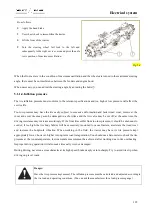
Turning the drawbar over can change height of the towing point to obtain a towing height suitable for the
mating implement.
Warning:
During operation, the drawbar can swing from side to side, but when the tractor tows the implement in
reverse direction, the 2 dowel pins must be inserted into the hole of the drawplate to keep the drawbar
standstill.
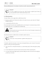
4.14.2.Towing device (configuration 1)
The hitch is suitable for all types of trailers, and cannot be used along with the swinging drawbar.
Содержание FL35-70HP Series
Страница 21: ...Product Mark 20 1 Security Considerations ...
Страница 57: ...Product Mark 56 Fig 1 35 Fig 1 36 ...
Страница 58: ...Product Mark 57 Fig 1 37 Fig 1 38 ...
Страница 62: ...Product Mark 61 Rear transverse board safety label To prevent personal injury do not ride or stand here ...
Страница 70: ...69 2 Product Mark ...
Страница 74: ...73 Page Left Intentionally Blank ...
Страница 75: ...Product Description 74 3 Product Description ...
Страница 77: ...Product Description 76 Fig 3 2 3 1 2 Appearance of tractor equipped with cab ...
Страница 81: ...Product Description 80 ...
Страница 84: ...Product Description 83 3 7 Notice Check whether the steering wheel is fixed firmly before driving ...
Страница 113: ...Product Description 112 ...
Страница 124: ...Electrical system 123 4 Operation Instructions ...
Страница 157: ...Electrical system 156 ...
Страница 162: ...Electrical system 161 Fig 4 32 Three point linkage Model 2 ...
Страница 168: ...Electrical system 167 Fig 4 41 Diagram for movement of the hitch mechanism configuration 3 Wheels ...
Страница 189: ...Electrical system 188 5 Wheels ...
Страница 208: ...Electrical system 207 6 Electrical System ...
Страница 230: ...Electrical system 229 requirements 6 6 Electrical Schematic Diagram ...
Страница 235: ...234 7 On board Spare Parts Tools and Quick wear Parts ...
Страница 241: ...240 ...
Страница 242: ...241 8 Maintenance Specification ...
Страница 288: ...287 Fig 8 35 ...
Страница 338: ...Operation Instructions 337 9 Troubleshooting ...
Страница 353: ...352 10 Tractor Storage and Unpack ...
Страница 358: ...Tractor Storage and Unpack 357 11 Delivery Acceptance and Transportation ...
Страница 361: ...360 ...
Страница 362: ...361 12 Disassembly and Disposal ...
Страница 365: ...Warranty Contents 364 13 Warranty Contents ...
Страница 411: ...Appendix 410 15 Appendix ...