


Electrical system
192
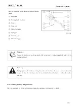
Do as follows
●
Apply the hand brake.
●
Use wheel chock to immobilize the tractor.
●
Lift the front of the tractor.
●
Turn the steering wheel full lock to the left and
subsequently to the right or vice versa and pivot the axle
to its position of maximum oscillation.
Fig. 5-4
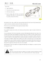
When the front axle is in the condition of maximum oscillation and the wheels are turned to the maximum steering
angle, there must be no interference between the fenders and engine hood.
When necessary, you can adjust the steering angle by adjusting the bolts
①
.
5.1.1.4.Inflation pressure
The tire inflation pressure must conform to the relevant specifications and too high or low pressure will affect the
service life.
Too low pressure may have the tire easily subject to excessive deformation and faster tread wear; moreover, the
inner and cover tires may even be damaged in a short time and the tire valve may be cut off; at the same time, the
driving resistance may increase accordingly. If the front tires suffer from too low pressure, it should be strenuous to
control; if too high, the tire body fabrics will be excessively tensioned to cause fracture, accelerate the tread wear
and increase the bodywork vibration. When working in the field, the tractor may have its tire pressure kept
appropriately lower; however, higher in long-term road transportation. You should use a barometer to check the tire
pressure at the room temperature, lest inaccurate measurement be achieved after working due to tire overheating.
Improper driving operation will also make tires early worn or damaged.
During driving, never run across obstacles at its high speed, brake deeply or turn sharply. Try to avoid tire slip when
driving on gravel roads.
Danger:
Have the tire pressure kept normal. The inflation pressure must be calculated and adjusted according to
the tire load and operating conditions. (You can ask the manufacturer for a load-pressure gauge)
Содержание FL35-70HP Series
Страница 21: ...Product Mark 20 1 Security Considerations ...
Страница 57: ...Product Mark 56 Fig 1 35 Fig 1 36 ...
Страница 58: ...Product Mark 57 Fig 1 37 Fig 1 38 ...
Страница 62: ...Product Mark 61 Rear transverse board safety label To prevent personal injury do not ride or stand here ...
Страница 70: ...69 2 Product Mark ...
Страница 74: ...73 Page Left Intentionally Blank ...
Страница 75: ...Product Description 74 3 Product Description ...
Страница 77: ...Product Description 76 Fig 3 2 3 1 2 Appearance of tractor equipped with cab ...
Страница 81: ...Product Description 80 ...
Страница 84: ...Product Description 83 3 7 Notice Check whether the steering wheel is fixed firmly before driving ...
Страница 113: ...Product Description 112 ...
Страница 124: ...Electrical system 123 4 Operation Instructions ...
Страница 157: ...Electrical system 156 ...
Страница 162: ...Electrical system 161 Fig 4 32 Three point linkage Model 2 ...
Страница 168: ...Electrical system 167 Fig 4 41 Diagram for movement of the hitch mechanism configuration 3 Wheels ...
Страница 189: ...Electrical system 188 5 Wheels ...
Страница 208: ...Electrical system 207 6 Electrical System ...
Страница 230: ...Electrical system 229 requirements 6 6 Electrical Schematic Diagram ...
Страница 235: ...234 7 On board Spare Parts Tools and Quick wear Parts ...
Страница 241: ...240 ...
Страница 242: ...241 8 Maintenance Specification ...
Страница 288: ...287 Fig 8 35 ...
Страница 338: ...Operation Instructions 337 9 Troubleshooting ...
Страница 353: ...352 10 Tractor Storage and Unpack ...
Страница 358: ...Tractor Storage and Unpack 357 11 Delivery Acceptance and Transportation ...
Страница 361: ...360 ...
Страница 362: ...361 12 Disassembly and Disposal ...
Страница 365: ...Warranty Contents 364 13 Warranty Contents ...
Страница 411: ...Appendix 410 15 Appendix ...