


325
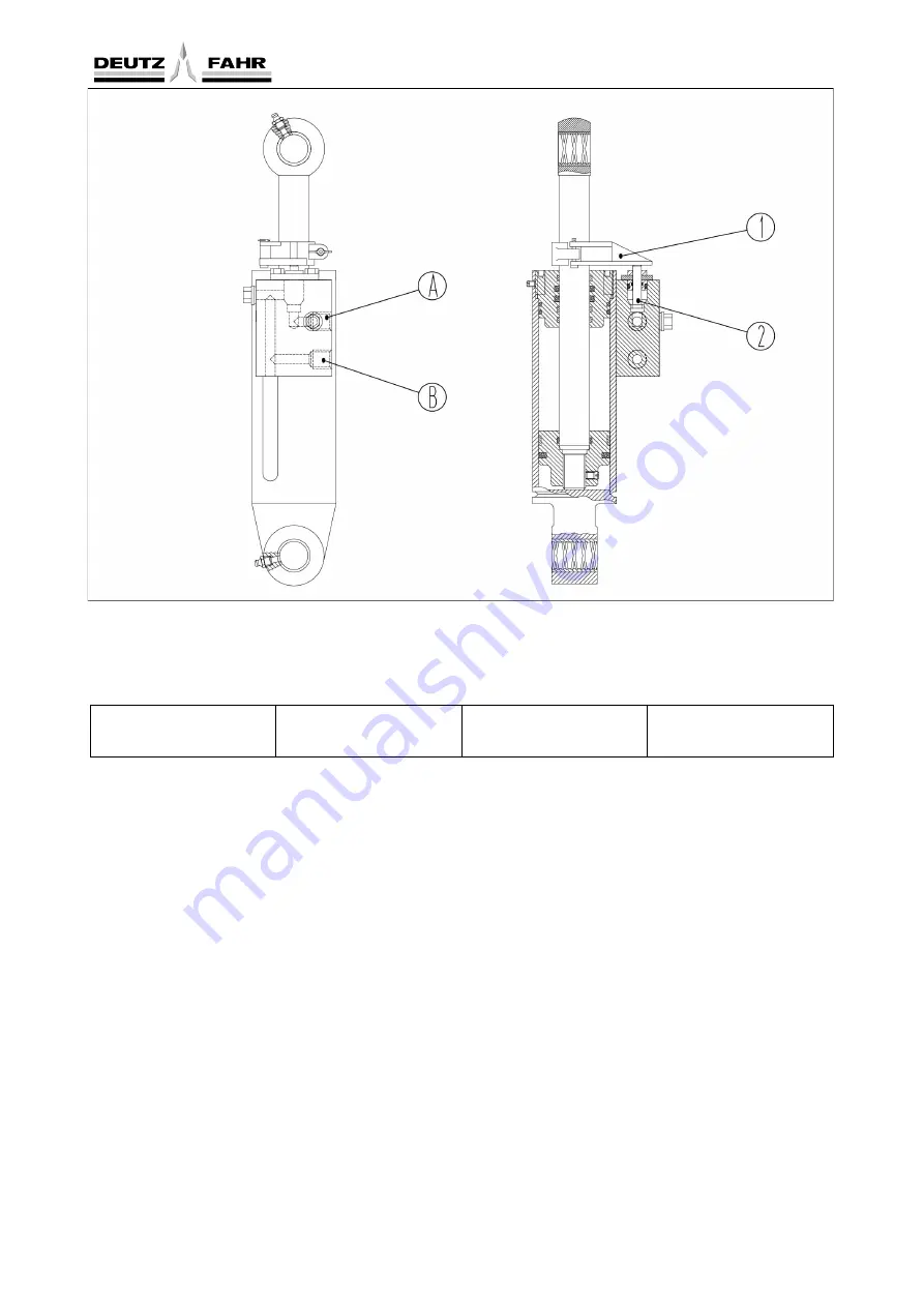
Fig. 8-72
Right lift cylinder assembly schematic
1.
Locating clamp;
2.
Locating valve;
A.
Lower oil port;
B.
Lift oil port;
●
Shift to transport status:
Lowering travel is determined by the positioning valves and positioning clip stoppers on the cylinders. The locating
clamp block can be vertically adjusted on the piston rod. The lower its position is, the smaller the lowering extent
is. The higher its position is, the larger the lowering extent is. During the lowering, if the locating valve is pushed
by the locating clamp block, the lowering is stopped.
●
Adjustment:
To guarantee the transport safety and reliability of implement, when the implement is lifted to the highest point,
adjust the locating clamp
①
to push down the locating adjustment valve
②
to the end and block the oil line of
cylinder lower chamber by locating valve, in order to prevent the further lowering.
Содержание FL35-70HP Series
Страница 21: ...Product Mark 20 1 Security Considerations ...
Страница 57: ...Product Mark 56 Fig 1 35 Fig 1 36 ...
Страница 58: ...Product Mark 57 Fig 1 37 Fig 1 38 ...
Страница 62: ...Product Mark 61 Rear transverse board safety label To prevent personal injury do not ride or stand here ...
Страница 70: ...69 2 Product Mark ...
Страница 74: ...73 Page Left Intentionally Blank ...
Страница 75: ...Product Description 74 3 Product Description ...
Страница 77: ...Product Description 76 Fig 3 2 3 1 2 Appearance of tractor equipped with cab ...
Страница 81: ...Product Description 80 ...
Страница 84: ...Product Description 83 3 7 Notice Check whether the steering wheel is fixed firmly before driving ...
Страница 113: ...Product Description 112 ...
Страница 124: ...Electrical system 123 4 Operation Instructions ...
Страница 157: ...Electrical system 156 ...
Страница 162: ...Electrical system 161 Fig 4 32 Three point linkage Model 2 ...
Страница 168: ...Electrical system 167 Fig 4 41 Diagram for movement of the hitch mechanism configuration 3 Wheels ...
Страница 189: ...Electrical system 188 5 Wheels ...
Страница 208: ...Electrical system 207 6 Electrical System ...
Страница 230: ...Electrical system 229 requirements 6 6 Electrical Schematic Diagram ...
Страница 235: ...234 7 On board Spare Parts Tools and Quick wear Parts ...
Страница 241: ...240 ...
Страница 242: ...241 8 Maintenance Specification ...
Страница 288: ...287 Fig 8 35 ...
Страница 338: ...Operation Instructions 337 9 Troubleshooting ...
Страница 353: ...352 10 Tractor Storage and Unpack ...
Страница 358: ...Tractor Storage and Unpack 357 11 Delivery Acceptance and Transportation ...
Страница 361: ...360 ...
Страница 362: ...361 12 Disassembly and Disposal ...
Страница 365: ...Warranty Contents 364 13 Warranty Contents ...
Страница 411: ...Appendix 410 15 Appendix ...