263
Fig. 8-8
1.
Main clutch
pedal
subassembly
2.
Pedal return spring;
3.
Draw bar
weldment
4.
Bolt
5.
Hex thin nut
6.
Adjustment pipe 7.
Left-handed-thread
draw bar weldment
8.
Return spring of
bearing block
9.
Release bearing
block
10.
Clutch
subassembly
●
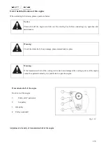
Adjustment of clutch
Due to wear of friction plates produced in use of the clutch, the clearance between the release lever end and the
release bearing end face decreases gradually even to zero. If this condition remains for a long term, this can result
in the release bearing overheat hence the clutch malfunction. Therefore, it is necessary to regularly check and adjust
the clearance.
➢
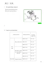
The gap between releasing lever and end clearance of release bearing of the clutch is between 2 and 2.5mm.
Height difference of end sockets of three releasing levers is not more than 0.2mm.
Adjustment: Loosen the lock nut. Turn the adjusting nut so that the clearance between three release levers and the
release bearing end face is (2 ~ 2.50) mm, and the height difference between the three release ends is less than
0.2mm. Then tighten the lock nut and adjusting nut.
125~135 (primary clutch
pedal travel)
200~220
(
total
travel
)
30-‐35(free travel)
Содержание FL35-70HP Series
Страница 21: ...Product Mark 20 1 Security Considerations ...
Страница 57: ...Product Mark 56 Fig 1 35 Fig 1 36 ...
Страница 58: ...Product Mark 57 Fig 1 37 Fig 1 38 ...
Страница 62: ...Product Mark 61 Rear transverse board safety label To prevent personal injury do not ride or stand here ...
Страница 70: ...69 2 Product Mark ...
Страница 74: ...73 Page Left Intentionally Blank ...
Страница 75: ...Product Description 74 3 Product Description ...
Страница 77: ...Product Description 76 Fig 3 2 3 1 2 Appearance of tractor equipped with cab ...
Страница 81: ...Product Description 80 ...
Страница 84: ...Product Description 83 3 7 Notice Check whether the steering wheel is fixed firmly before driving ...
Страница 113: ...Product Description 112 ...
Страница 124: ...Electrical system 123 4 Operation Instructions ...
Страница 157: ...Electrical system 156 ...
Страница 162: ...Electrical system 161 Fig 4 32 Three point linkage Model 2 ...
Страница 168: ...Electrical system 167 Fig 4 41 Diagram for movement of the hitch mechanism configuration 3 Wheels ...
Страница 189: ...Electrical system 188 5 Wheels ...
Страница 208: ...Electrical system 207 6 Electrical System ...
Страница 230: ...Electrical system 229 requirements 6 6 Electrical Schematic Diagram ...
Страница 235: ...234 7 On board Spare Parts Tools and Quick wear Parts ...
Страница 241: ...240 ...
Страница 242: ...241 8 Maintenance Specification ...
Страница 288: ...287 Fig 8 35 ...
Страница 338: ...Operation Instructions 337 9 Troubleshooting ...
Страница 353: ...352 10 Tractor Storage and Unpack ...
Страница 358: ...Tractor Storage and Unpack 357 11 Delivery Acceptance and Transportation ...
Страница 361: ...360 ...
Страница 362: ...361 12 Disassembly and Disposal ...
Страница 365: ...Warranty Contents 364 13 Warranty Contents ...
Страница 411: ...Appendix 410 15 Appendix ...


