


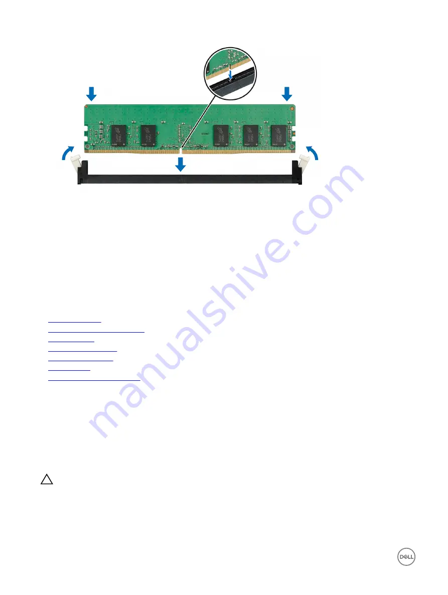
Figure 26. Installing a memory module
Next steps
1.
Install the air shroud.
2.
Install the sled into the chassis.
3.
Follow the procedure listed in the After working inside your system section.
4.
To enter
System Setup
, press F2 and check the
System Memory
setting.
5.
If the value is incorrect, one or more of the memory modules may not be installed properly. Ensure that the memory modules
are firmly seated in the sockets.
6.
Run the system memory test in the system diagnostics.
Related links
Safety instructions
Before working inside your system
Removing a sled
Removing the air shroud
Installing the air shroud
Installing a sled
After working inside your system
1.8-inch Solid State Drive
A solid state drive (SSD) is a data storage device used for storing and retrieving digital information.
Each sled supports one internal 1.8-inch SSD.
Removing the 1.8-inch solid state drive
Prerequisites
CAUTION: Many repairs may only be done by a certified service technician. You should only perform troubleshooting and
simple repairs as authorized in your product documentation, or as directed by the online or telephone service and support
team. Damage due to servicing that is not authorized by Dell is not covered by your warranty. Read and follow the safety
instructions that are shipped with your product.
1.
Follow the safety guidelines listed in the Safety instructions section.
2.
Follow the procedure listed in the Before working inside your system section.
72
Содержание PowerEdge C6320p
Страница 1: ...Dell PowerEdge C6320p Owner s Manual Regulatory Model B08S Series Regulatory Type B08S004 ...
Страница 10: ...Figure 2 Supported configuration for the C6320p sled with an Intel Phi 72xx processor 10 ...
Страница 11: ...Figure 3 Supported configuration for the C6320p sled with an Intel Phi 72xx F processor 11 ...
Страница 25: ...Figure 16 Enclosure Service Tag location on the left front panel 25 ...
Страница 106: ...Figure 55 Removing an expansion card filler bracket 106 ...
Страница 152: ...Figure 95 Installing PDB 2 Figure 96 Installing the power cables and the power cable cover for PDB 2 152 ...


