


Steps
1.
Locate the TPM connector on the system board.
NOTE: To locate the TPM connector on the system board, see the System board connectors section.
2.
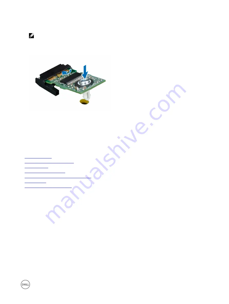
Align the edge connectors on the TPM with the slot on the TPM connector.
3.
Insert the TPM into the TPM connector such that the plastic rivet aligns with the slot on the system board.
4.
Press the plastic rivet until the rivet snaps into place.
Figure 73. Installing the TPM
Next steps
1.
If removed, install the mezzanine card.
2.
Install the sled into the enclosure.
3.
Follow the procedure listed in the After working inside your system section.
Related links
Safety instructions
Before working inside your system
Removing a sled
Removing a mezzanine card
PowerEdge C6320p system board connectors
Installing a sled
After working inside your system
Initializing the Trusted Platform Module
1.
While booting your system, press F2 to enter System Setup.
2.
On the
System Setup Main Menu
screen, click
System BIOS
→
System Security Settings
.
3.
From the
TPM Security
option, select
On with Pre-boot Measurements
.
4.
From the
TPM Command
option, select
Activate
.
5.
Save the settings.
6.
Restart the sled.
System board
A system board (also known as the motherboard) is the main printed circuit board in the system with different connectors used to
connect different components or peripherals of the system. A system board provides the electrical connections to the components
in the system to communicate.
127
Содержание PowerEdge C6320p
Страница 1: ...Dell PowerEdge C6320p Owner s Manual Regulatory Model B08S Series Regulatory Type B08S004 ...
Страница 10: ...Figure 2 Supported configuration for the C6320p sled with an Intel Phi 72xx processor 10 ...
Страница 11: ...Figure 3 Supported configuration for the C6320p sled with an Intel Phi 72xx F processor 11 ...
Страница 25: ...Figure 16 Enclosure Service Tag location on the left front panel 25 ...
Страница 106: ...Figure 55 Removing an expansion card filler bracket 106 ...
Страница 152: ...Figure 95 Installing PDB 2 Figure 96 Installing the power cables and the power cable cover for PDB 2 152 ...


