


68
SM-Universal Encoder Plus User Guide
www.controltechniques.com
Issue Number: 6
Performance object parameters
The encoder can contain up to 2 performance objects each of which contains a set of
parameters that can be used to give different levels of motor performance.
It should be noted that the data within the objects in the encoder is undefined until it has
been written and that the manufacturer’s data is undefined until it has been written by a
complete motor object write with Pr
3.49
set to one. If a value stored in the nameplate
data exceeds the maximum of a parameter when the data is transferred the parameter
in the drive is not updated.
The checksum for each object is Zero – sum of bytes in the object excluding the
checksum itself. The number of bytes defines the number of bytes used to generate the
checksum. This includes all the parameters and the number of bytes parameter, and so
this value will always be 62 for the motor object and 30 for a performance object.
When either a motor or performance object is transferred to the drive all drive
parameters are saved. When a performance object is loaded the speed control gain
select parameter is automatically set to zero. Therefore either the speed controller gains
defined in the performance object or those derived from the compliance angle,
bandwidth and damping factor parameters are used.
Encoder cable length
The allowable encoder cable length is determined / specified by either:
•
The encoder manufacturer
•
The cable manufacturer (specified transmission delay and line attenuation rating).
Data sampling - transmission delays
The encoder begins setting the data up on the falling edge of the clock. The Unidrive SP
samples the data line level on the rising edge of the clock. The maximum permissible
delay between the clock falling edge at the drive and the data being correct at the drive
is thus half the clock period.
The delay is made up of the transmission delays of:
•
The clock signal down the line to the encoder
•
The encoder data set up time
•
The transmission delay of the data level returning from the encoder to the drive.
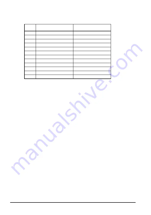
Pr
Performance object 1
Description
Performance object 2
Description
3.10
Speed controller Kp gain
Speed controller Kp gain
3.11
Speed controller Ki gain
Speed controller Ki gain
3.12
Speed controller Kd gain
Speed controller Kd gain
3.17
Speed controller set-up method
Speed controller set-up method
3.19
Compliance angle
Compliance angle
3.20
Bandwidth
Bandwidth
3.21
Damping factor
Damping factor
4.05
Motoring current limit
Motoring current limit
4.06
Regen current limit
Regen current limit
4.12
Torque demand filter
Torque demand filter
4.13
Current controller Kp gain
Current controller Kp gain
4.14
Current controller Ki gain
Current controller Ki gain
Содержание SM-Universal Encoder Plus
Страница 73: ...SM Universal Encoder Plus User Guide 73 Issue Number 6 www controltechniques com ...
Страница 112: ...0471 0005 06 ...