-
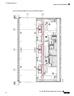
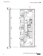
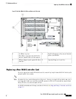
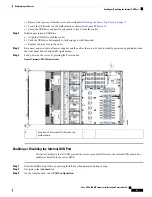
Supercap bracket location on inner chassis
wall (view of the front compartment shown
is with the CPU modules removed)
1
Replacing a Rear (Internal) Drive-Bay Module
The optional, rear drive-bay module provides eight drive bays.
When the rear drive-bay module is used, PCIe slot 12 is not available because there is not enough clearance.
Note
When the rear drive-bay module is populated with SAS/SATA drives, the air diffuser must be installed.
Note
Step 1
Shut down and remove power from the server as described in
Shutting Down and Removing Power From the Server, on
page 35
.
Step 2
Slide the server out the front of the rack far enough so that you can remove the top cover. You might have to detach
cables from the rear panel to provide clearance.
If you cannot safely view and access the component, remove the server from the rack.
Caution
Step 3
Remove the top cover from the server as described in
Removing the Server Top Cover, on page 37
.
Step 4
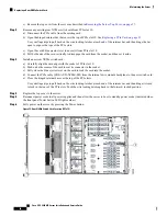
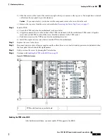
Remove any existing rear drive-bay module:
a) Remove any drives from the existing rear drive-bay module and set them aside.
b) If the air diffuser is present on the module, remove the diffuser. Lift straight up on the diffuser and set it aside.
It is not necessary to remove the rear supercap unit from the diffuser.
c) Disconnect any cable from a RAID controller or NVMe switch card from the module connectors.
d) Loosen the two screws that secure the module to the chassis.
e) Grasp the module at each end and lift up evenly to disengage its connector from the socket on the motherboard.
Step 5
Install a new rear drive-bay module:
a) While holding the new module level, align it over the socket on the motherboard and the two screw-holes.
b) Gently press the module connector to the motherboard socket. Stop when the module frame sits flat over the
screw-holes.
c) Install the two screws that secure the module to the chassis.
d) Connect any cable from a RAID card or NVMe switch card to the new module backplane.
e) Reinstall the air diffuser to the module if you removed one earlier (required only if the module is populated with
SAS/SATA drives).
In a system with only one CPU module, an additional filler panel is required in PCIe slot 11 to ensure
adequate air flow. See
Replacing a Rear RAID Controller Card, on page 77
for more information.
Note
f)
Install your drives to the bays in the new module.
Cisco UCS C480 M5 Server Installation and Service Guide
72
Maintaining the Server
Replacing a Rear (Internal) Drive-Bay Module
Содержание UCS C480 M5
Страница 30: ...Cisco UCS C480 M5 Server Installation and Service Guide 28 Installing the Server Accessing the System BIOS ...
Страница 134: ...Cisco UCS C480 M5 Server Installation and Service Guide 132 Server Specifications Server Specifications ...
Страница 162: ...Cisco UCS C480 M5 Server Installation and Service Guide 160 GPU Card Installation GPU Card Installation ...


