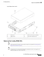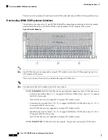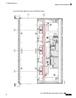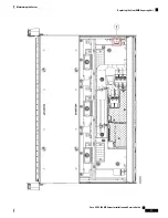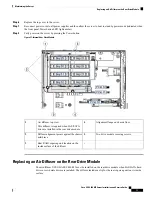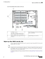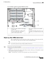
Thumbscrews that secure drive bay modules
(one each module)
3
Front of server (view of front compartment
shown with both CPU modules removed)
1
Chassis brace
2
Replacing a Front RAID Controller Card
For detailed information about storage controllers in this server, see
Supported Storage Controllers and Cables,
on page 133
.
The server supports one front RAID controller card for control of up to 24 front-loading SAS/SATA drives.
The card installs to a dedicated, horizontal socket on the chassis midplane. The socket is below the CPU
modules and can be accessed from the top of the server after the CPU modules are removed.
Firmware on the storage controller must be verified for compatibility with the current Cisco IMC and BIOS
versions that are installed on the server. If not compatible, upgrade or downgrade the storage controller
firmware using the Host Upgrade Utility (HUU) for your firmware release to bring it to a compatible level.
See the HUU guide for your Cisco IMC release for instructions on downloading and using the utility to bring
server components to compatible levels:
HUU Guides
.
Step 1
Prepare the server for component installation:
a) Shut down and remove power from the server as described in
Shutting Down and Removing Power From the Server,
on page 35
.
b) Slide the server out the front of the rack far enough so that you can remove the top cover. You might have to detach
cables from the rear panel to provide clearance.
If you cannot safely view and access the component, remove the server from the rack.
Caution
c) Remove the top cover from the server as described in
Removing the Server Top Cover, on page 37
.
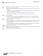
Step 2
Remove all CPU modules from the chassis to provide clearance:
a) Grasp the two ejector levers on the module and pinch their latches to release the levers.
b) Rotate both levers to the outside at the same time to evenly disengage the module from the midplane connectors.
c) Pull the module straight out from the chassis and then set it on an antistatic surface.
Step 3
Remove any existing front RAID controller card from the server:
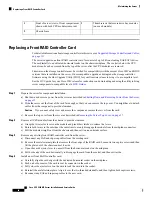
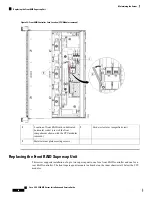
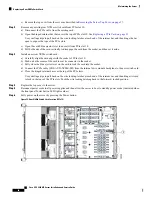
a) Disconnect any SAS and supercap cables from the existing card.
b) Remove the metal retainer plate that secures the front edge of the RAID card. Loosen its two captive screws and then
lift the plate out of the chassis and set it aside.
c) Open the card's ejector lever to unseat it from the horizontal socket on the midplane.
d) Pull both ends of the card horizontally to disengage the card from the socket, and then set it aside.
Step 4
Install a new front RAID controller card:
a) Carefully align the card edge with the dedicated horizontal socket on the midplane.
b) Push on both corners of the card to seat its connector in the socket.
c) Fully close the ejector lever on the card to lock the card into the socket.
d) Reinstall the metal retainer plate. Align it over the two threaded standoffs, and then tighten both captive screws.
e) Reconnect any SAS and supercap cables to the new card.
Cisco UCS C480 M5 Server Installation and Service Guide
66
Maintaining the Server
Replacing a Front RAID Controller Card
Содержание UCS C480 M5
Страница 30: ...Cisco UCS C480 M5 Server Installation and Service Guide 28 Installing the Server Accessing the System BIOS ...
Страница 134: ...Cisco UCS C480 M5 Server Installation and Service Guide 132 Server Specifications Server Specifications ...
Страница 162: ...Cisco UCS C480 M5 Server Installation and Service Guide 160 GPU Card Installation GPU Card Installation ...


