


Mode
name
Standby
mode
APC mode
APC mode / Print mode
Forcible
OFF mode
Standby
mode
LaserA
PSTBY
PSTBY
PINTR
At 1st line (APC)
LSTR
instruction
Image formation
ready timing
Printer
status
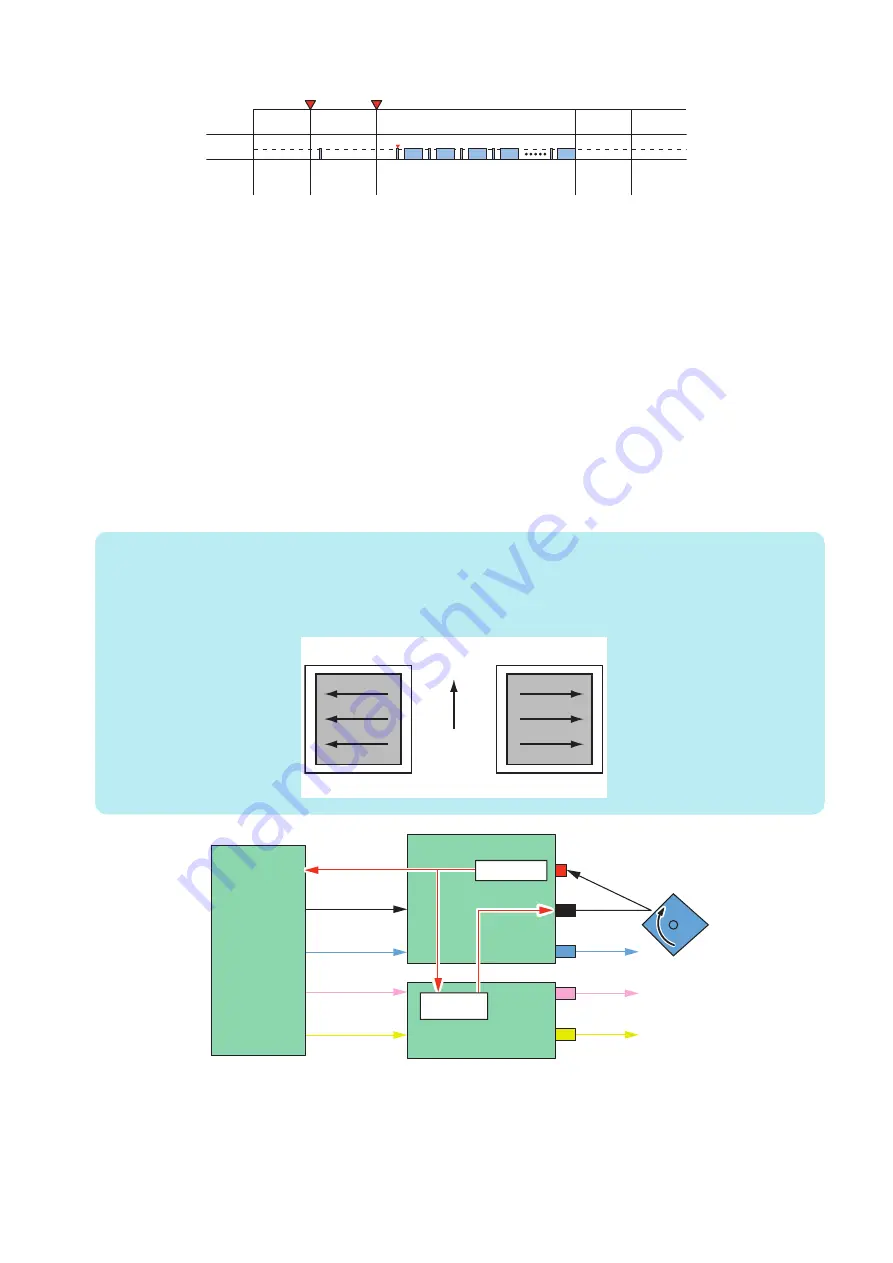
■ Horizontal scanning synchronous control
Purpose
Aligns the write start position in the horizontal scanning direction.
Execution Timing
When printing is started (for each line)
Control description
1. The Y/M Laser Driver PCB forcibly emits the Bk laser diode of the C/Bk Laser Driver PCB by setting the Bk laser control
signal to APC mode.
2. The laser beam of the Bk laser has a BD circuit in the scanning light path, and is incident on the BD Circuit.
3. The BD Circuit detects the laser beam and generates a BD signal, and sends it to the Main Controller.
4. The Main Controller synchronizes with this signal, and sends video signals (Y_VDO, M_VDO, C_VDO and Bk_VDO) to the
Y/M and C/Bk Laser Driver PCBs while regarding the reference BD signal as the vertical scanning synchronous signal (BD)
for each line. This enables each Laser Driver PCB to emit a laser beam from a fixed position for each line.
NOTE:
• As the BD signal is the horizontal scanning synchronous signal of the Bk color, the Bk color serves as each color's
reference for horizontal scanning.
• With this machine, the reference in the horizontal scanning direction for Y and M colors is the right edge (right-to-left)
while that for C and Bk colors is the left edge (left-to-right).
<Y, M color>
<C, Bk color>
Right standard
Left standard
Feeding
direction
Y_VDO
M_VDO
C_VDO
Bk_VDO
Main Controller
PCB(UN05)
Y Laser
M Laser
C Laser
Bk Laser
BD Signal
C/K Laser Driver PCB
(UN09)
BD Sensor
Y/M Laser Driver
PCB(UN08)
ASIC
APC Signal
■ Vertical Scanning Synchronization Control
Purpose
Aligns the write start position in the vertical scanning direction.
2. Technology
57
Содержание imageRUNNER ADVANCE C3330 Series
Страница 1: ...Revision 7 0 imageRUNNER ADVANCE C3330 C3325 C3320 Series Service Manual ...
Страница 18: ...Product Overview 1 Product Lineup 7 Features 11 Specifications 17 Parts Name 26 ...
Страница 278: ...J1335 J1066 J1022 J1146 J1050 J1051 J130 J1052 J1053 J1333 J120 J128 J130 4 Parts Replacement and Cleaning 266 ...
Страница 326: ...CAUTION Check that the color of the seal at the center is black 4 Parts Replacement and Cleaning 314 ...
Страница 359: ...6 Remove the Bottle Drive Unit 1 2 Bosses 2 5 Hooks 3 2 2 3 3 3 2 2 1 3 3 3 3 4 Parts Replacement and Cleaning 347 ...
Страница 399: ...Adjustment 5 Pickup Feed System 388 Document Exposure System 391 Actions after Replacement 393 ...
Страница 518: ...Error Jam Alarm 7 Overview 507 Error Code 511 Jam Code 617 Alarm Code 624 ...
Страница 1020: ...9 Installation 1008 ...
Страница 1022: ...2 Perform steps 3 to 5 in each cassette 9 Installation 1010 ...
Страница 1024: ...5 6 Checking the Contents Cassette Feeding Unit 1x 3x 2x 1x 9 Installation 1012 ...
Страница 1027: ...3 4 NOTE The removed cover will be used in step 6 5 2x 2x 9 Installation 1015 ...
Страница 1046: ...When the Kit Is Not Used 1 2 Close the Cassette 2 When the Kit Is Used 1 9 Installation 1034 ...
Страница 1058: ...3 4 CAUTION Be sure that the Inner 2 way Tray Support Member is installed properly 9 Installation 1046 ...
Страница 1062: ...Installation procedure 1 NOTE The work is the same when the Utility Tray is installed 9 Installation 1050 ...
Страница 1068: ... Removing the Covers 1 2x 2 1x 9 Installation 1056 ...
Страница 1070: ...3 1x 1x 9 Installation 1058 ...
Страница 1080: ...Installation Outline Drawing Installation Procedure 1 Remove the all tapes from this equipment 2 2x 9 Installation 1068 ...
Страница 1081: ...3 CAUTION To avoid damage do not pull the A part of the Utility Tray too much A 4 9 Installation 1069 ...
Страница 1083: ...6 7 TP M4x8 2x 2x 9 Installation 1071 ...
Страница 1084: ...When Installing the USB Keyboard 1 Cap Cover Wire Saddle 9 Installation 1072 ...
Страница 1095: ...9 2x 10 2x 11 Remove the Face Seals from the Reader Right Cover The removed Face Seals will not be used 9 Installation 1083 ...
Страница 1101: ... When Stopping to Use 1 Press Reset key or the Voice Recognition button for more than 3 seconds 9 Installation 1089 ...
Страница 1129: ...9 2x 10 2x 11 9 Installation 1117 ...
Страница 1135: ...Remove the covers 1 ws 2x 2 1x 9 Installation 1123 ...
Страница 1140: ...2 2x 3 Connect the power plug to the outlet 4 Turn ON the power switch 9 Installation 1128 ...
Страница 1155: ...Installation Outline Drawing Installation Procedure Removing the Covers 1 2x 2 1x 9 Installation 1143 ...
Страница 1157: ...3 Connect Power Cable and Signal Cable disconnected in the step 2 to the Encryption Board 2 Connectors 2x 9 Installation 1145 ...
Страница 1167: ...Installation Procedure Removing the Covers 1 2x 2 1x 3 2x Installing the Removable HDD Kit 9 Installation 1155 ...
Страница 1176: ... A 2x Installing the Covers 1 1x 2 2x 9 Installation 1164 ...
Страница 1177: ...3 4 2x Installing the Removable HDD 1 Install the HDD Unit to the HDD Slot 9 Installation 1165 ...
Страница 1182: ...Installation Outline Drawing Installation Procedure Removing the Covers 1 2x 2 1x 9 Installation 1170 ...
Страница 1190: ...14 Install the Cable Guide to the HDD Frame 4 Hooks 1 Boss 9 Installation 1178 ...
Страница 1195: ...23 Secure the Power Cable in place using the Wire Saddle 1x Installing the Covers 1 1x 2 2x 9 Installation 1183 ...
Страница 1196: ...3 4 2x Installing the Removable HDD 1 Install the HDD Unit to the HDD Slot 9 Installation 1184 ...


