


Package
Describing the same item number also on the part's package enhances the association between the part and the host machine
at the user site.
GENUINE
'5
4XDQWLW\⹈兂₹㟿4XDQWLW«⏴㟿
0DGHLQ-DSDQ)DEULTX« DX-DSRQℶ⦿㡴㦻
㻭㻰㻲⤥⣬䝻䞊䝷䞊䛸ศ㞳䝟䝑䝗
$')3LFNXS5ROOHU $') 6HSDUDWLRQ 3DG
5RXOHDXSULVHSDS &$' 7DPSRQ V«SDU&$'
5XOORGLSUHVDGHOO$') 6HSDUDWRUH GHOO$')
$XIQDKPHZDO]H $') 6HSDUDWLRQVSDG $')
5RGLOORGHUHFRJLGD GH$') 6HSDUDGRU GH$')
$')鞾덵 ꈙꆡ $')ꜹꍡ 볝麑
呹┷戢䳎⣷㚢兇戙 呹┷戢䳎⣷⒕䱊䓖
5ROHWH$SDQKDGRU GR$OLPHQWDGRU $XWRP£WLFRGH'RFXPHQWRV
%DVHGH6HSDUD©¥R GR$OLPHQWDGRU $XWRP£WLFRGH'RFXPHQWRV
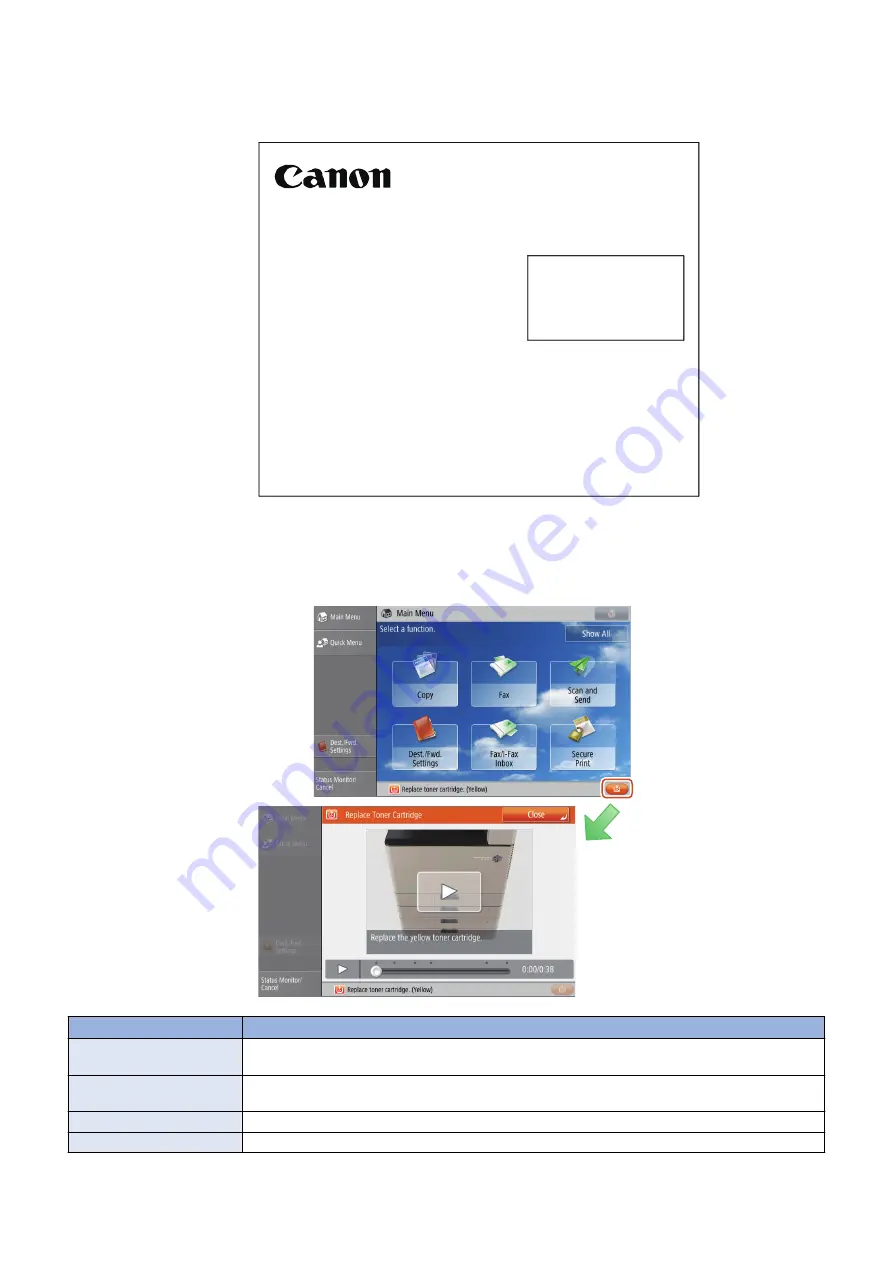
■ Maintenance Video for Consumables Replacement
Videos are adopted to guide users with an easy-to-understand navigation of the replacement so that they can replace parts
correctly without performing any wrong operation.
Item
Display timing
Toner Container
When the toner becomes empty (For Bk, it is forcibly displayed by pop-up. For YMC, it is displayed when
the button at the bottom right is pressed since printing using only BK is still possible).
Waste Toner Container
"An orange button appears when ""Waste toner is near full. Replacement not yet needed"" is displayed.
When completely full, it is forcibly displayed by pop-up."
Staples
Displayed by pop-up if there are no staples the next time stapling is executed
Drum Unit *1
A button appears when 7 days have elapsed since the specified drum life value (*2) was reached.
*1: Can be displayed only in the case of COPIER > OPTION > USER > P-CRG-LF=1
1. Product Overview
14
Содержание imageRUNNER ADVANCE C3330 Series
Страница 1: ...Revision 7 0 imageRUNNER ADVANCE C3330 C3325 C3320 Series Service Manual ...
Страница 18: ...Product Overview 1 Product Lineup 7 Features 11 Specifications 17 Parts Name 26 ...
Страница 278: ...J1335 J1066 J1022 J1146 J1050 J1051 J130 J1052 J1053 J1333 J120 J128 J130 4 Parts Replacement and Cleaning 266 ...
Страница 326: ...CAUTION Check that the color of the seal at the center is black 4 Parts Replacement and Cleaning 314 ...
Страница 359: ...6 Remove the Bottle Drive Unit 1 2 Bosses 2 5 Hooks 3 2 2 3 3 3 2 2 1 3 3 3 3 4 Parts Replacement and Cleaning 347 ...
Страница 399: ...Adjustment 5 Pickup Feed System 388 Document Exposure System 391 Actions after Replacement 393 ...
Страница 518: ...Error Jam Alarm 7 Overview 507 Error Code 511 Jam Code 617 Alarm Code 624 ...
Страница 1020: ...9 Installation 1008 ...
Страница 1022: ...2 Perform steps 3 to 5 in each cassette 9 Installation 1010 ...
Страница 1024: ...5 6 Checking the Contents Cassette Feeding Unit 1x 3x 2x 1x 9 Installation 1012 ...
Страница 1027: ...3 4 NOTE The removed cover will be used in step 6 5 2x 2x 9 Installation 1015 ...
Страница 1046: ...When the Kit Is Not Used 1 2 Close the Cassette 2 When the Kit Is Used 1 9 Installation 1034 ...
Страница 1058: ...3 4 CAUTION Be sure that the Inner 2 way Tray Support Member is installed properly 9 Installation 1046 ...
Страница 1062: ...Installation procedure 1 NOTE The work is the same when the Utility Tray is installed 9 Installation 1050 ...
Страница 1068: ... Removing the Covers 1 2x 2 1x 9 Installation 1056 ...
Страница 1070: ...3 1x 1x 9 Installation 1058 ...
Страница 1080: ...Installation Outline Drawing Installation Procedure 1 Remove the all tapes from this equipment 2 2x 9 Installation 1068 ...
Страница 1081: ...3 CAUTION To avoid damage do not pull the A part of the Utility Tray too much A 4 9 Installation 1069 ...
Страница 1083: ...6 7 TP M4x8 2x 2x 9 Installation 1071 ...
Страница 1084: ...When Installing the USB Keyboard 1 Cap Cover Wire Saddle 9 Installation 1072 ...
Страница 1095: ...9 2x 10 2x 11 Remove the Face Seals from the Reader Right Cover The removed Face Seals will not be used 9 Installation 1083 ...
Страница 1101: ... When Stopping to Use 1 Press Reset key or the Voice Recognition button for more than 3 seconds 9 Installation 1089 ...
Страница 1129: ...9 2x 10 2x 11 9 Installation 1117 ...
Страница 1135: ...Remove the covers 1 ws 2x 2 1x 9 Installation 1123 ...
Страница 1140: ...2 2x 3 Connect the power plug to the outlet 4 Turn ON the power switch 9 Installation 1128 ...
Страница 1155: ...Installation Outline Drawing Installation Procedure Removing the Covers 1 2x 2 1x 9 Installation 1143 ...
Страница 1157: ...3 Connect Power Cable and Signal Cable disconnected in the step 2 to the Encryption Board 2 Connectors 2x 9 Installation 1145 ...
Страница 1167: ...Installation Procedure Removing the Covers 1 2x 2 1x 3 2x Installing the Removable HDD Kit 9 Installation 1155 ...
Страница 1176: ... A 2x Installing the Covers 1 1x 2 2x 9 Installation 1164 ...
Страница 1177: ...3 4 2x Installing the Removable HDD 1 Install the HDD Unit to the HDD Slot 9 Installation 1165 ...
Страница 1182: ...Installation Outline Drawing Installation Procedure Removing the Covers 1 2x 2 1x 9 Installation 1170 ...
Страница 1190: ...14 Install the Cable Guide to the HDD Frame 4 Hooks 1 Boss 9 Installation 1178 ...
Страница 1195: ...23 Secure the Power Cable in place using the Wire Saddle 1x Installing the Covers 1 1x 2 2x 9 Installation 1183 ...
Страница 1196: ...3 4 2x Installing the Removable HDD 1 Install the HDD Unit to the HDD Slot 9 Installation 1184 ...


